
Components Voltage Tester Circuit Schematic
This circuit operates as a versatile testing tool for audio equipment and voltage verification. The core functionality relies on a low-frequency oscillator configuration, where transistors Q1 and Q2 act as the oscillating elements. The oscillation frequency is dependent on the load resistance, providing a range of frequencies suitable for testing different types of audio equipment. The output signal is designed to be audible, facilitating quick diagnostics of speaker phasing and performance.
In practical applications, the circuit can be utilized in various environments, including home audio systems, car audio installations, and public address systems. The ability to drive multiple speakers directly on a high-voltage line system (100V or 70V) enhances its utility in large setups, ensuring that technicians can efficiently verify the operation of numerous speakers simultaneously.
The inclusion of visual indicators, such as the LED that flashes with each pulse, adds an additional layer of functionality. This feature allows users to quickly ascertain the load status, ensuring that components are functioning as expected. The voltage indicator circuit, consisting of LED2, diode D3, and zener diode ZD1, provides a convenient means of checking for adequate voltage levels, which is particularly beneficial in automotive applications where voltage fluctuations can occur.
Overall, this circuit design is well-suited for audio technicians and engineers, providing an efficient and effective method for testing and verifying the performance of various audio components. Its simplicity and reliability make it an essential tool for anyone involved in audio equipment installation and maintenance.This simple circuit tests speakers, microphones, transformers and voltage. It`s basically a very low frequency oscillator that produces extremely short fruity` pulses. The type of sound produced is very easy to hear and to determine the precise direction it is coming from, thus making it ideal for checking the phasing in multiple speaker installat ions. It is also very useful for car stereo installations as well as public address systems where it can drive dozens of speakers directly on a 100V or 70V line system. The signal is also easy to hear on a public address system so that you can drive around a large installation with the window down and easily hear each speaker as you drive past.
It is easy to check that a speaker is in phase with its neighbours, by listening for the artificial centre created between two identical sound sources. Q1 and Q2 oscillate when connected to loads between zero and about 1000O. The frequency increases as the resistance of the load increases 8O loads produce about 8Hz output while 100O loads will produce about 100Hz output, although it is only approximate.
The unit is also useful for checking dynamic microphones (not condenser types), headphones, transformers (both audio and mains) and resistance loads (only visual checks via the LED). The pulses produced can sound too loud for some delicate circuits such as dynamic microphones and headphones, but the pulse is so short that it is virtually impossible to do any damage; the average current flow is only a few milliamps.
The circuit needs no power switch as the oscillator only operates when the negative side of the battery is connected through the load being tested. The LED flashes at each pulse as a visual indication that the load is lower than about 1000O. The circuit works from a 3V battery pack. To use a 9V battery change the 15O resistor to 47O, the 1. 8O resistor to 5. 6O and the. 033 µF capacitor to. 01 µF. LED2, diode D3, zener diode ZD1 and the series 220O resistor form a voltage indicator which is used to detect and indicate any voltage greater than about 10V.
LED2 only illuminates if the voltage rises above the threshold set by ZD1 and D1, which is more than the battery voltage (3V or 9V). These components can be omitted if the device is not going to be used for working on cars. However, it`s quite handy having a device that can check power wires, shorts to chassis and speakers in a car.
🔗 External reference
Related Circuits
This is a fire alarm system utilizing the IC TD2002 suite to detect fire incidents. The alarm is crucial in residential complexes, allowing for early detection. It operates by detecting fog generated by fire, which reduces the light reaching...
There have been numerous inquiries regarding this project, primarily due to issues with the source code provided at the end of the author's notes. This problem has been widely reported online, and similar compilation errors have been encountered. It...
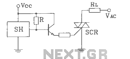
SH Hall opened with a double silicon output interface circuit The SH Hall sensor circuit is designed to provide a dual silicon output interface, which enables enhanced signal processing capabilities. This circuit typically integrates a Hall effect sensor that detects...
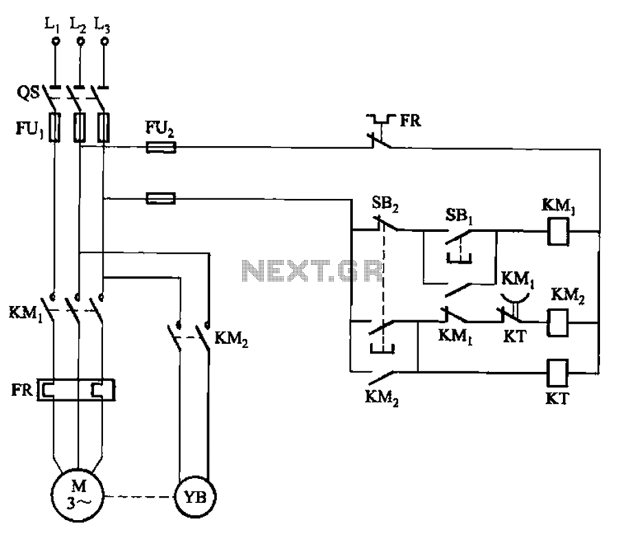
The circuit illustrated in Figure 3-123 operates as follows: When the stop button SBz is pressed, contact KMi releases, cutting off power to the motor. Simultaneously, KMz is activated, engaging the electromagnetic brake YB to hold the motor in...
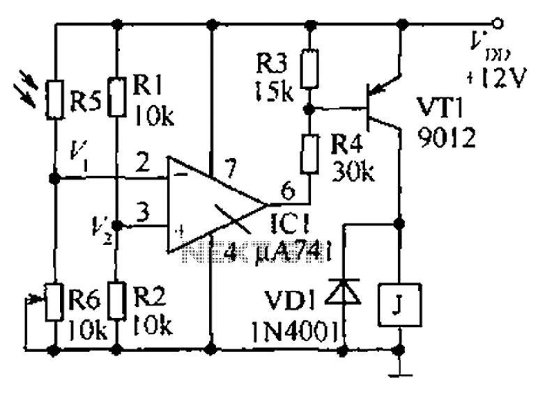
The circuit functions as a precision bright light control circuit, operating independently of variations in power supply voltage and ambient temperature. Resistors R1, R2, R6, and the photosensitive resistor R5 form a two-arm Wheatstone bridge. The precision bright light control...
This circuit is essentially a crystal radio equipped with an audio amplifier that demonstrates considerable sensitivity, successfully receiving multiple strong stations in the Los Angeles area using a minimal 15-foot antenna. Employing a longer antenna can enhance signal strength;...