
car and motorcycle battery tester
The described circuit serves as a battery monitoring system designed to assess the charge level of lead-acid batteries commonly used in camping and automotive applications. The circuit typically incorporates a microcontroller or an analog voltage divider to measure the battery voltage. The measured voltage is then compared against predefined thresholds to determine the state of charge (SoC) of the battery.
For a 12 V lead-acid battery, the circuit may include a voltage regulator to ensure that the microcontroller operates within its specified voltage range. The voltage reading from the battery is converted into a digital value using an Analog-to-Digital Converter (ADC), allowing for precise monitoring. The microcontroller can be programmed to display the battery status on an LCD screen or through LED indicators, providing clear visual feedback to the user.
In addition, the circuit may feature an alarm system that triggers when the battery voltage falls below a critical threshold, signaling the need for recharging. This is particularly useful during camping trips, where access to charging facilities may be limited. For motorcycle applications, the same principles apply, with adjustments made for the lower 6 V battery system.
Overall, this battery monitoring circuit enhances the convenience and reliability of using lead-acid batteries in outdoor activities, ensuring that users can maintain their electronic devices without the worry of unexpected power loss.Going camping nowadays involves taking lots of electronic equipment whether for day to day running or for fun and entertainment. Most of the time a charged lead acid battery and a power inverter would be used to ensure a smoothly organized holiday where ideally the missus and the children cheerfully use their electric and electronic gear!
With rechargeable lead-acid batteries it s invariably useful - if not essential - to determine whether the power source you re hauling along on your travels is losing capacity and needs to be topped up. The same circuit would also come in handy when going on a car or motorbike trip as it can check the status of a 12 V (car) or a 6 V (motorcycle) battery..
🔗 External reference
Related Circuits
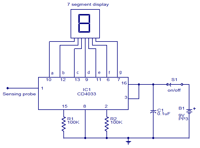
This circuit is designed to test the presence of mains voltage without direct electrical contact with the mains line. The core component of this circuit is the CMOS IC CD4033, which features a five-stage decade Johnson counter and an...
This circuit is designed for use with inductive pick-up elements and dynamic microphones. Most soundcards feature a line input and a dedicated input for electret (condenser) microphones. To connect an inductive tape recorder head or a dynamic microphone, an...
This design features a signal logic tester that utilizes a common cathode seven-segment display. The display indicates a logic level "1" (represented by an "H" on the display) or a logic level "0" (represented by an "L" on the...
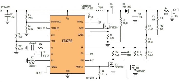
This Sealed Lead Acid Battery Charger is designed using the LT3755 DC-DC controller. The LT3755 is a DC-DC controller that operates as a constant-current source and supports a wide input voltage range from 4.5 to 40 volts, providing a...
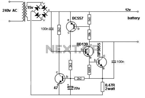
A simple 12V battery charger circuit can be designed using a TIP3055 power transistor to limit the current to the battery. The circuit turns off when the battery voltage reaches approximately 14V or if the current exceeds 2A. This...
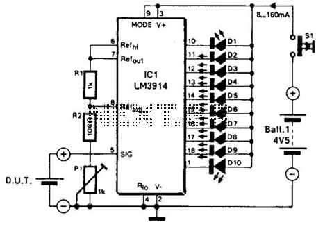
The LM3914A bar graph LED is utilized as a voltmeter for testing batteries. This circuit operates on a 4.5-V battery and compares the battery under test with an internally generated reference, established by resistors R1, R2, and potentiometer P1....