
Car Antenna Amplifier Circuit
The car antenna amplifier circuit is designed to enhance the reception capabilities of antenna systems, particularly in automotive applications. With a gain of approximately 30 dB, the amplifier significantly boosts weak signals, making it ideal for environments where signal strength is compromised. The input impedance of around 10 kΩ at 30 MHz ensures compatibility with a wide range of antennas, allowing for effective signal transfer without loading the antenna excessively.
To maximize performance and minimize signal loss, the amplifier must be installed directly at the antenna's base. This installation approach mitigates the effects of cable capacitance, which can degrade signal quality, particularly at higher frequencies. The use of high-quality coaxial cables with low loss characteristics further enhances the overall efficiency of the system.
For outdoor applications, the importance of housing the amplifier in a waterproof enclosure cannot be overstated. Environmental factors such as moisture and temperature fluctuations can adversely affect the performance and longevity of electronic components. Therefore, utilizing a robust, weatherproof case will protect the amplifier from the elements, ensuring reliable operation over extended periods.
It is crucial to note that this amplifier is specifically designed for receiver antennas. Attempting to use it for transmitting signals can lead to irreversible damage to the amplifier and potentially the connected equipment. Proper installation and adherence to the intended use of the amplifier will ensure optimal performance and longevity of the system.The total gain of the car antenna amplifier is around 30 dB and the input impedance at 30 Mhz is around 10 K ©. The amplifier must be mounted directly at the base of the antenna to avoid signal losses caused by the capacitive character of the coaxial cable.
This antenna amp must be used for non-mobile recievers. If you intend to install this circu it in you outdoor mounted antenna, make sure that is housed in a water proof case. Use this car antenna amp circuit only for receiver antennas. Transmitting through it will damage the components. 🔗 External reference
Related Circuits
Hens require adequate illumination to increase egg production rates. To counteract the reduced winter sunlight, poultry farms commonly utilize artificial lighting in coops. For instance, the circuit depicted in Figure 297 can automatically provide light at night. The light...
Low distortion bass and treble control for an amplifier. Circuit diagram. Electronics project. The low distortion bass and treble control circuit is designed to enhance the audio quality of an amplifier by allowing precise adjustments to the low and high-frequency...
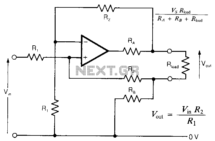
In intrinsically safe applications, it is sometimes necessary to separate sections of circuitry using resistors that limit current under fault conditions. The circuit presented offers an accurate analog output with effectively zero output impedance, despite the presence of resistors...
The LM383 schematic represents an 8-watt audio amplifier, which is straightforward to construct as a mini-audio power amplifier. The parts list includes the following components: C1 - 1 unit of a 10µF electrolytic capacitor, C2 - 1 unit of...
This simple and inexpensive circuit built around a popular CMOS hex inverter IC CD4069UB offers four sequential switching outputs that may be used to control 200 LEDs (50 LEDs per channel), driven directly from mains supply. Input supply of...
This universal power supply includes a bridge rectifier, a voltage stabilizer (78xx), and a PNP power transistor. This combination allows for a load current output. The universal power supply circuit is designed to convert alternating current (AC) from the mains...