
Universal Power Supply Circuit
The universal power supply circuit is designed to convert alternating current (AC) from the mains into a stable direct current (DC) output suitable for various electronic applications. The bridge rectifier serves as the initial component, consisting of four diodes arranged in a configuration that allows both halves of the AC waveform to be utilized, effectively converting AC to pulsating DC.
The voltage stabilizer, typically represented by the 78xx series, is a linear voltage regulator that maintains a constant output voltage despite variations in input voltage or load conditions. The "xx" in the designation indicates the specific output voltage, which can range from 5V to 24V depending on the model used. The stabilizer's output is connected to the load, ensuring that sensitive electronic components receive a consistent voltage level.
The inclusion of a PNP power transistor in this circuit enhances its current handling capabilities. This transistor acts as a switch or amplifier, allowing for increased load current without overheating or causing voltage drops. When combined with the voltage regulator, the PNP transistor provides additional stability and current support, making the power supply suitable for driving higher power devices.
Overall, this universal power supply design is versatile and can be adapted for various applications, including powering microcontrollers, sensors, and other electronic circuits that require a reliable and stable power source. Proper heat sinking and component selection are critical to ensure efficient operation and longevity of the power supply system.This universal power supply contains, beside the bridge rectifier, a voltage stabilizer (78xx) and a pnp power transistor. This combination allow a load cu.. 🔗 External reference
Related Circuits
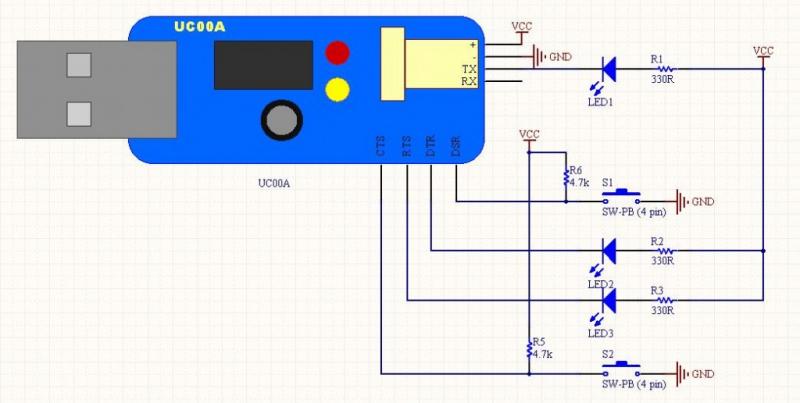
The LEDs operate in an active-low configuration (0), while the initial state of the switches is high (1). In other words, the PC software must send a low signal (0) to activate the LEDs, and if a low signal...
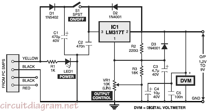
Variable desktop power supply that converts a high input voltage (12V) from the SMPS/PSU of a desktop computer into a small output voltage (1.25V to 9V). The variable desktop power supply is designed to provide adjustable output voltages ranging from...
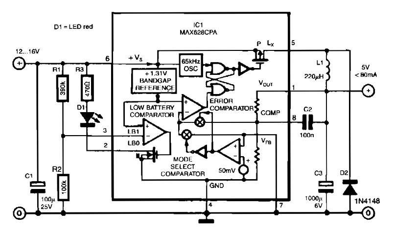
The circuit utilizes the MAX638CPA 5V CMOS Step Down Adjustable Switching Regulator IC, which converts an input voltage of 12 to 16 VDC into a stable 5VDC output. It requires only nine additional external components to complete the circuit....
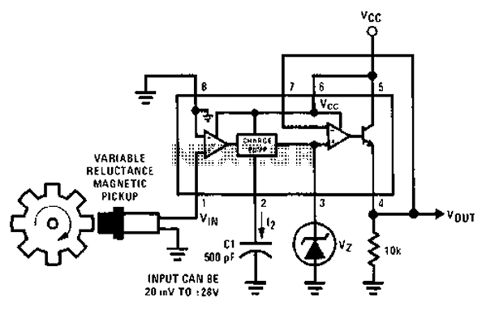
After each zero electromagnetic pickup receives a sine wave input, as illustrated in the National Semiconductor LM2907 circuit, it generates an output pulse. This circuit can be utilized in digital control systems. The width of each pulse corresponds to...
High power amps are not too common as projects, since they are by their nature normally difficult to build, and are expensive. A small error during assembly means that you start again - this can get very costly. I...
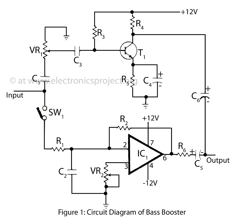
The bass booster featured on this website enhances the beat frequency while maintaining the integrity of the high-frequency response. The circuit diagram for the bass booster, along with various radio circuits, is also provided. The bass booster circuit operates by...
Warning: include(partials/cookie-banner.php): Failed to open stream: Permission denied in /var/www/html/nextgr/view-circuit.php on line 713
Warning: include(): Failed opening 'partials/cookie-banner.php' for inclusion (include_path='.:/usr/share/php') in /var/www/html/nextgr/view-circuit.php on line 713