
Simple Electronic Fan Regulator Circuit PCB
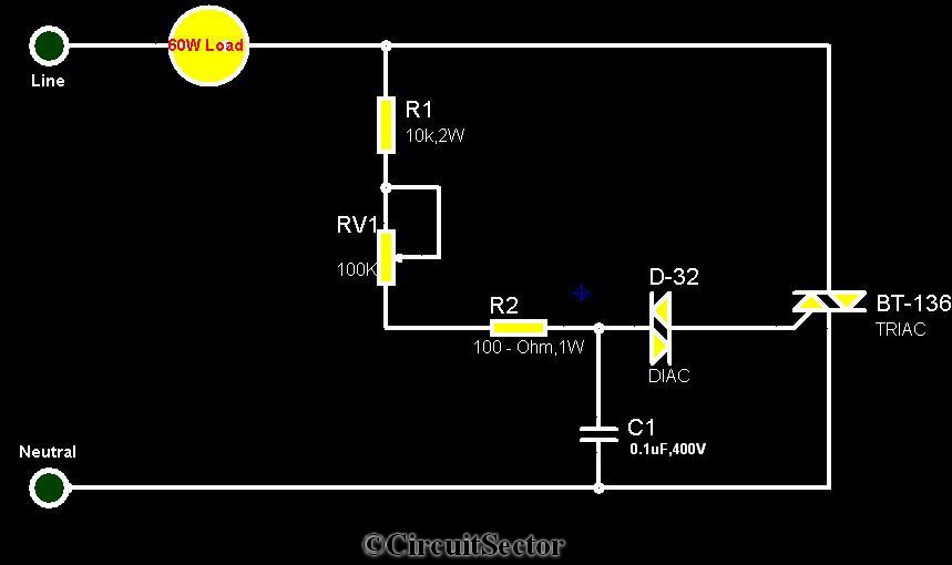
The triac-diac electronic fan regulator circuit is an efficient solution for controlling the speed of electric fans while minimizing energy consumption. The circuit utilizes a triac, a type of semiconductor device that can conduct current in both directions when triggered. The control of the triac is achieved through a diac oscillator, which serves as a triggering device. The D-32 diac is a key component that allows the circuit to switch on at a specific voltage level, providing a sharp transition that enhances the control of the triac.
The resistors R1 and R2 are used to set the biasing conditions for the diac, while the variable resistor RV1 allows for fine-tuning of the oscillator's time period. This adjustment directly affects the firing angle of the triac, which determines how much of the AC waveform is allowed to pass through to the fan motor. By controlling the amount of power delivered to the motor, the fan speed can be effectively regulated without the significant energy losses associated with traditional methods.
The capacitor (0.1uF 400V) in the circuit plays a crucial role in determining the oscillation frequency of the diac. Its value, in conjunction with the resistors, sets the timing characteristics of the oscillator, which in turn influences the firing angle of the triac. The overall design of the circuit emphasizes minimal heat generation and efficient power usage, making it suitable for applications where energy efficiency is a priority.
In summary, the triac-diac electronic fan regulator circuit provides a sophisticated method for adjusting fan speeds, leveraging the properties of triacs and diacs to achieve precise control while maintaining energy efficiency. The ability to adjust the firing angle through the diac oscillator allows for smooth and gradual changes in fan speed, enhancing user comfort and reducing electrical consumption.Circuit The circuit diagram provided is a triac - diac electronic fan regulator that would reduce your power usage of electric fans even in slow speeds. A normal resistor-inductor fan regulator heats up to waste eneegy when the fan is running with lowers speeds or it controls motor speed via applying resistance between fan and power supply.
This l ight dimmer/fan regulator circuit uses the principle of power control using a Tric. The triac turns On and Off varying the firing angle of the Triac. This can be done by a diac oscillator circuit. The diac oscillator consists of D-32 diac, R1, RV1, R2 resistors, a 0. 1uF 400V capacitor. The time period of this diac oscillator can be controlled by adjusting RV1. By doing this we can vary the firing angle of the triac thus the speed of the fan motor. 🔗 External reference
Related Circuits

This design features a simple yet effective receiver with good sensitivity and selectivity. The circuit utilizes a compact three-transistor regenerative receiver with fixed feedback, primarily based on the BC549 transistor. The tuned circuit is intended for medium wave frequencies...
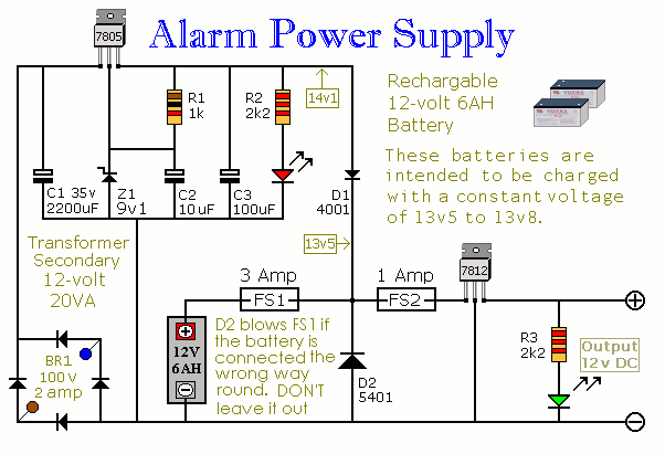
This power supply is designed for the Modular Burglar Alarm but is suitable for various applications. It delivers a 12-volt output with a maximum current of 1 amp. In case of a mains failure, the backup battery activates immediately,...
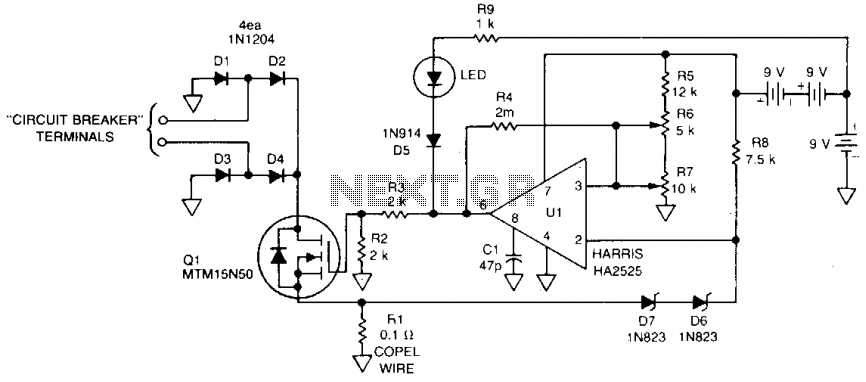
This 115 Vac electronic circuit breaker utilizes the low drive power, low on-resistance, and fast turn-off characteristics of the TMOS MTM15N50. The trip point is adjustable, and an LED fault indication is provided, with battery power ensuring complete circuit...
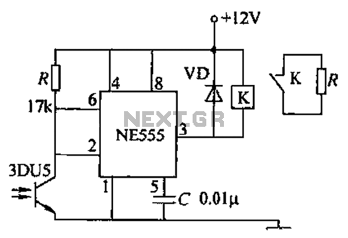
A transmitting circuit powered by an infrared light-emitting diode emits light. The receiving circuit, shown in the figure, utilizes a transistor (3DU5) to receive the infrared light and output the received signal. The signal is sent to terminal 3...
A field effect transistor amplifier features a fixed bias input source with feedback, resulting in very high input impedance and low capacitance. It drives a field effect transistor or emitter follower, despite having a very low output impedance, utilizing...
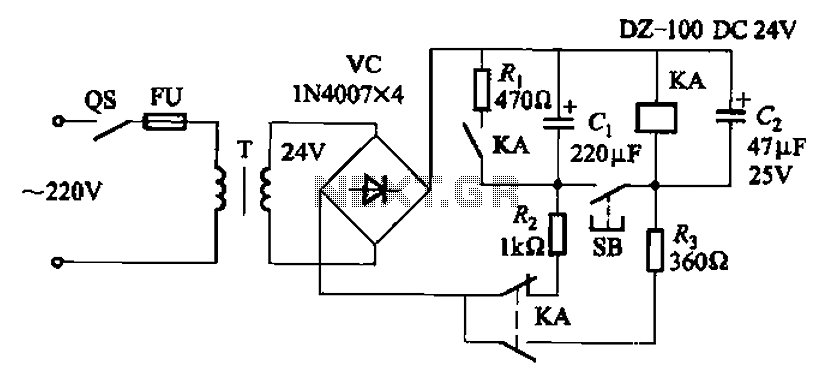
After the turn-off circuit is first applied to the next KA KA, the intermediate interval required is less than Is. This is due to the time needed, which is equal to three times the charge time constant of the...