
Chager circuit for SMF batteries
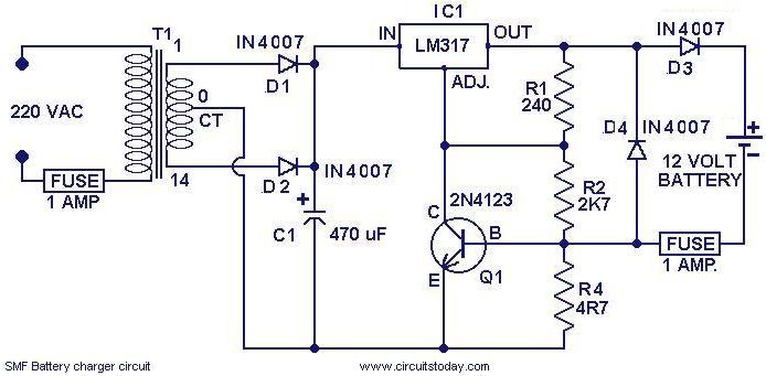
The charger circuit operates as follows: The transformer T1 steps down the AC voltage from the mains supply to a lower AC voltage suitable for charging. Diodes D1 and D2 are configured in a bridge rectifier arrangement, converting the AC voltage to a pulsating DC voltage. Capacitor C1 smooths this pulsating DC voltage, providing a more stable output for the subsequent regulation stages.
The regulation section consists of an integrated circuit (IC1), which is typically a voltage regulator, and a transistor (Q1) that is used to handle the required current. This configuration allows the circuit to maintain a consistent output voltage and current, essential for safely charging the battery without overcharging or damaging it.
Diode D3 is crucial as it prevents any backflow of current from the battery to the charger when the charger is not in operation, thus protecting the circuit components. The resistor R4 is a key component in determining the charging current. By using the formula R4 = (0.6 V / Charging current), it is possible to calculate the appropriate resistance value needed to achieve the desired charging current for different battery types. For instance, if a charging current of 100 mA is required, R4 would need to be approximately 6 ohms.
Overall, this charger circuit is a versatile solution for charging various SMF batteries, with the ability to adjust charging parameters through simple modifications. Proper attention to component ratings and configurations will ensure reliable and safe operation.Here is a simple charger circuit for charging SMF(sealed maintenance free ) batteries. The charger circuit being curernt and voltage regulated, can be safely used to charge SMF batteries of 1. 2 AH rating. This circuit was actually designed in response to a request from a reader. With slight modifications you can use it for charging any sort of SMF bat teries. The first part of the circuit is the power supply made of transformer T1 and diodes D1&D2. The capacitor C1 filters the rectifier output. The next part is the section comprising of IC1 and Q1 which provides the necessary volatge and current regulation. The diode D3 prevents ther reverse flow of charge from the battery. R4 is the component that determines the charging current. Here it is set to be 120 mA. R4= (0. 6 V/Charging current). By selecting the proper value of R4 according to equation, you can charge batteries that require different charging currents.
🔗 External reference
Related Circuits
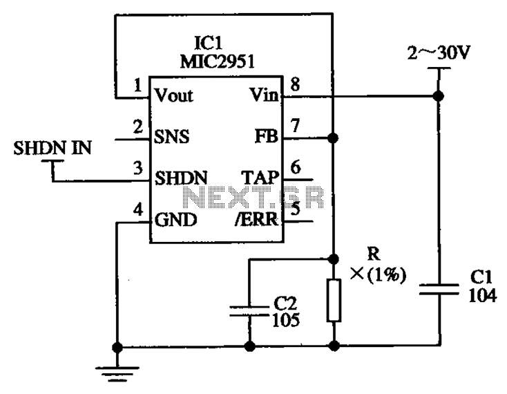
The circuit illustrated in the figure utilizes the low-drift current source circuit MIC2951, which is designed to provide specific output current values. The MIC2951 is a precision voltage regulator that can also be configured to function as a low-drift current...
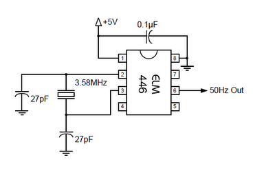
The ELM446 is an 8-pin digital divider integrated circuit that generates both 50Hz and 1Hz outputs from a common 3.58MHz NTSC colorburst crystal. The designer needs to supply only the crystal and two suitable loading capacitors, along with a...
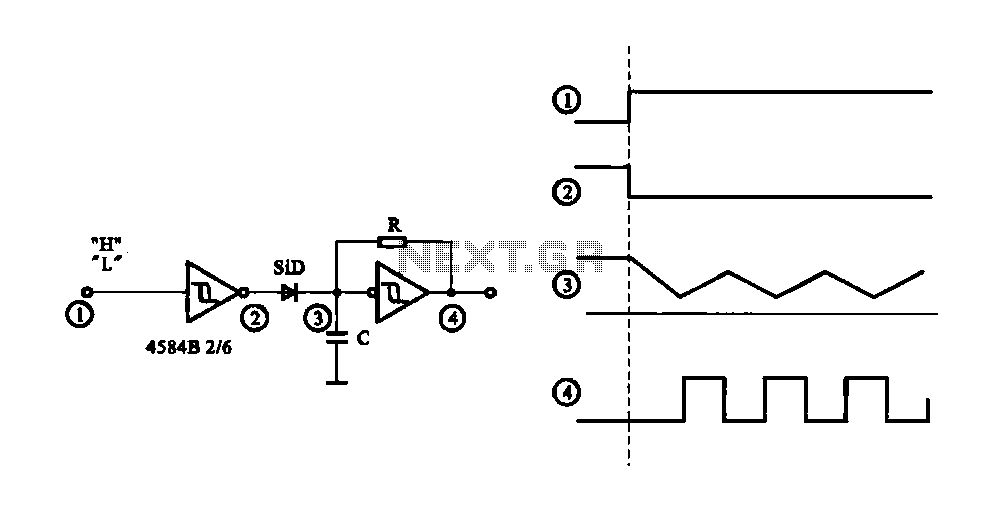
The circuit generates a controlled pulse signal. When a high pulse signal is applied to the input terminal O (start), the output pulse signal is activated. Conversely, when a low signal is received at the input terminal O (stop),...
A 5-minute circuit can continue to operate during a power outage, providing protection for the refrigerator. The refrigerator power protection circuit, designated as 1136, includes a power transformer that converts 220V voltage through a rectifier bridge (VD1). This setup...
This quartz crystal oscillator circuit exhibits greater stability compared to a parallel resonance circuit. It is capable of generating frequencies up to 30 MHz or even higher when utilizing BFR91 transistors for T1 and T2, along with reduced values...
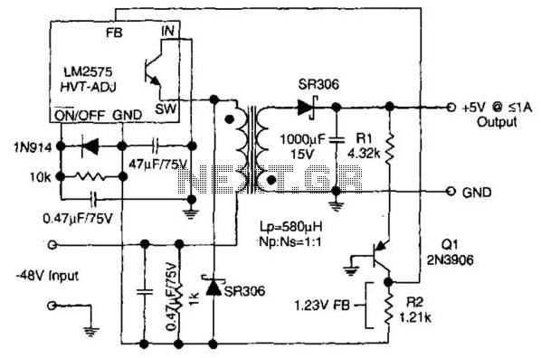
The circuit supplies 1 A at +5 V from the -48 V supply commonly used in telephone equipment. More: The National Semiconductor LM2575 is a simple switching regulator. The circuit utilizes the National Semiconductor LM2575, which is a step-down (buck)...