
Car Battery Charger
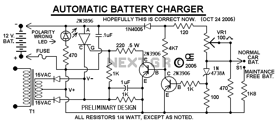
The Transformer, Diodes and SCR, Must be capable of handling the output current. And Don't use a 10 amp transformer. If you expect to charge batteries at 10 amps, Allow yourself a Safety margin! Use a 15 Amp transformer. Also, the Diodes and SCR will Definitely require a Suitable, LARGE Heat Sink!
The 100 ohm trimpot on the PCB sets the Maximum Charge Voltage. To set this Correctly, attach a Fully charged battery to the output. Then using a meter to monitor the output, set the trimpot to give an output of 14.5 volts at Very Near ZERO CURRENT.
A Center Tapped Transformer and two Diodes are shown, but a Single output, 16 Volt transformer could be used with a full wave bridge rectifier.
Some manufacturers recommend chargers with a Low Output, AC Ripple content. If this concerns you, you can add a large Filter Cap across the output. However, this Capacitor will NOT be Protected by a reversed battery, unless it is connected before the fuse in that line.
This charger circuit is designed specifically for charging batteries and cannot function as a power supply without a battery connected. The circuit includes a reverse polarity indicator to prevent damage from incorrect battery connections. The operation begins with the connection of a battery, which is mandatory for the charger to output power. Prior to connecting the charger to the mains voltage (110V), the battery must be connected. If the battery is mistakenly connected in reverse, the reverse polarity LED will illuminate, signaling the error. It is critical to correct the battery connection before applying mains voltage to avoid potential damage to the circuit.
The design specifies that a suitable fuse should be included in the output line to protect against overcurrent conditions, and it is advisable to use an additional fuse for the line input. The transformer selected for this charger must be capable of handling the expected output current; a 15 Amp transformer is recommended for charging batteries at 10 Amps to provide a safety margin. The diodes and SCR in the circuit must also be rated appropriately and should be mounted on a large heat sink to dissipate heat effectively during operation.
A 100 ohm trimpot is integrated into the PCB, allowing for the adjustment of the maximum charge voltage. To set this voltage accurately, a fully charged battery should be connected, and the output monitored with a multimeter to achieve a voltage of 14.5 volts at minimal current draw.
For rectification, a center-tapped transformer and two diodes can be utilized, although an alternative configuration with a single 16 Volt transformer and a full-wave bridge rectifier is also feasible. Additionally, if low AC ripple output is a concern, a large filter capacitor can be added across the output. However, it is crucial to ensure that this capacitor is connected before the fuse in the circuit to safeguard against damage from reverse battery connections.This Charger Can't be used as a Power Supply, Without having a battery in place. The Battery MUST be Connected to get power out. Note: This Charger Features a Reverse polarity Indicator. Instructions: Before plugging this charger into the 110 volt line (or turning it on if you use a Switch), FIRST Connect this Charger to the Battery. In doing so, No Damage will occur if the battery is accidently connected in reverse, but the Reverse Polarity LED will light up.
If that LED Does light, Reconnect the battery Correctly, than apply the 110 line voltage. Connecting the Line voltage, With a reversed battery connection, WILL Result in Damage. Especially if you don't use the fuse on the output, as shown in the schematic. Although Not Shown in the schematic, A suitable Line fuse would also be advisable. There is No Amp-Meter shown, But I would Definately recommend including one in either the positive or negative line, going to the battery. The Transformer, Diodes and SCR, Must be caplable of handling the output current. And Don't use a 10 amp transformer. If you expect to charge battery's at 10 amps, Allow youself a Safety margin! Use a 15 Amp transformer. Also the Diodes and SCR will Definately require a Suitable, LARGE Heat Sink! The 100 ohm trimpot on the PCB sets the Maximum Charge Voltage. To set this Correctly, attach a Fully charged battery to the output. Than using a meter to monitor the output,Set the trimpot to give an output of 14.5 volts at Very Near ZERO CURRENT.
I Show a Center Tapped Transformer and two Diodes, But a Single output, 16 Volt transformer could be use with a full wave bridge rectifier. Some manufacturers recommend Charges with a Low Output, AC Ripple content. If this concerns you, You can add a large Filter Cap across the output. However this Capacitor will NOT be Protected by a reversed battery, unless it is connect before the fuse in that line.
🔗 External reference
Related Circuits
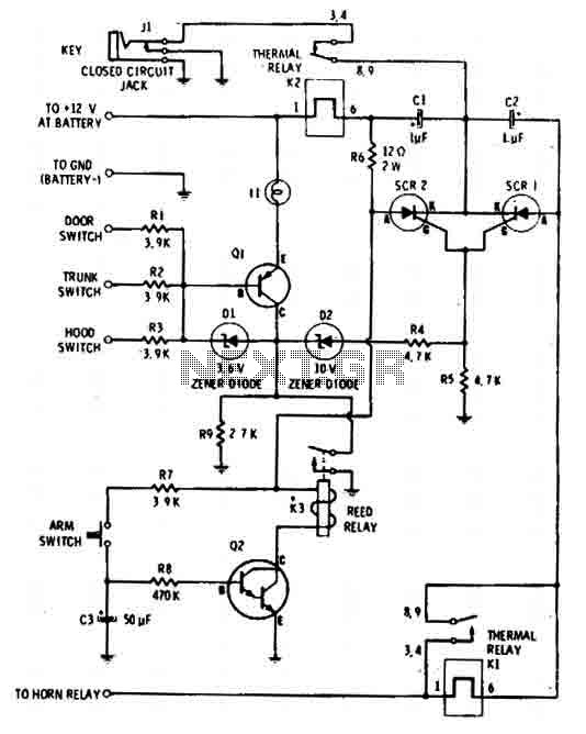
The car alarm is a straightforward circuit with fundamental features that monitor all entry points of the vehicle, such as doors, using switches. It operates with a single switch (the arm switch) that allows the circuit to remain inactive...
Camping today often involves various electronic accessories for daily activities or entertainment. Typically, a portable battery charger and a power inverter are used to ensure a well-organized campsite where both adults and children can comfortably use their electronic devices....
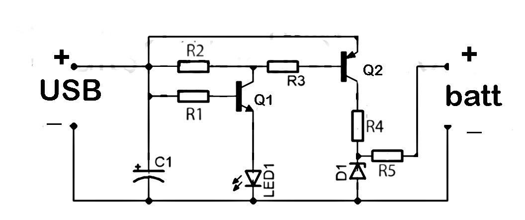
This document discusses the series used in USB connections for charging batteries. The output voltage ranges from 4.7 volts to 5 volts DC, which is suitable for charging mobile phones and other battery types. The circuit described enhances the...
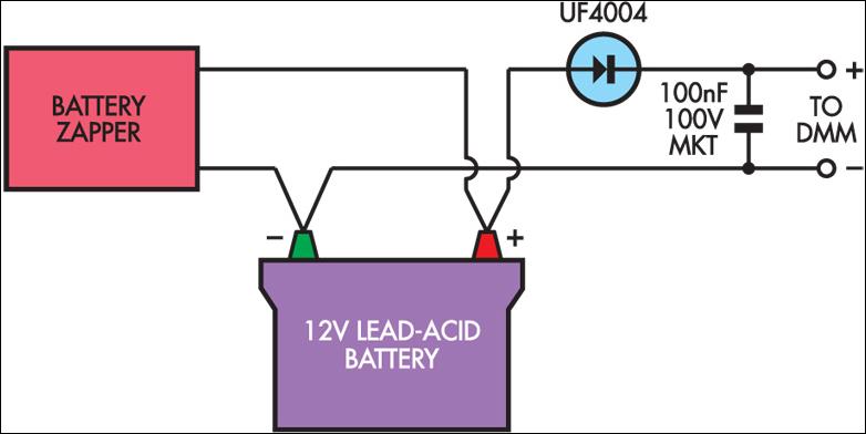
Several readers have inquired about how to determine when the Lead-Acid Battery Zapper has effectively completed the desulphation process. Based on the author's experience, batteries that are responsive to this treatment typically exhibit a notably high peak voltage across...
An LM556 dual oscillator/timer, U1, configured as a two-tone oscillator drives U2, a dual 4-watt amplifier. One of the oscillators, pins 1 to 6, contained in U1 produces the upper frequency signal of about 200 Hz, while the second...
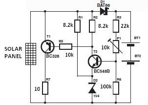
The nominal voltage of the solar charger circuit module is determined by the number of battery cells to be charged. Due to the typical voltage drop of 0.3 to 0.4 V across Schottky diode D1, the nominal voltage should...