
solar charger circuit diagram
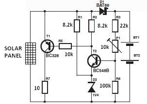
The solar charger circuit module operates based on the configuration of its components and the characteristics of the solar panel. The nominal voltage is crucial as it dictates the charging capability for the battery cells. The Schottky diode D1 is essential in this circuit, as it introduces a voltage drop that must be accounted for in the design. When selecting the nominal voltage, it is necessary to ensure that it exceeds the set charge voltage on potentiometer P1 by the voltage drop amount, which ranges from 0.3 to 0.4 V.
The solar panel, composed of eight solar cells connected in series, generates a combined output voltage of approximately 3.6 V under optimal sunlight conditions. The current output can vary between 140 mA and 200 mA, influenced by the specific solar panel characteristics and environmental factors.
To prevent overcharging of the batteries, the circuit employs a mechanism that activates a power resistor when the voltage reaches the full charge threshold. This action effectively reduces the output voltage of the solar panel, thereby ceasing the charging process and protecting the batteries from potential damage due to overvoltage. The integration of these components and their operational thresholds ensures a reliable and efficient solar charging system.The nominal voltage of the solar charger circuit module is determined by the number of battery cells to be charged. Because of the typical voltage drop of 0. 3 to 0. 4 V across Schottky diode D1, the nominal voltage should exceed the charge voltage set on P1 by about 0.
3 0. 4 V. The solar panel for this project is a typical solar module that consi sts of eight series connected solar cells. In sunshine the solar panel will supply about 140 mA -200mA or more( depends of the solar panel used ) at 8 times 0. 45 V = 3. 6 V. When the voltage rises above a certain level (full charge ), a power resistor is switched in parallel with the solar panel, which causes output voltage of the solar panel to drop and stops the batteries from being charged.
🔗 External reference
Related Circuits
This hybrid circuit uses a mixture of transistors, an IC and a relay and is used to automatically open or close a pair of curtains. Using switch S3 also allows manual control, allowing for curtains to be left only...

A 2x22 W car audio amplifier circuit utilizes the TDA1558, a monolithic integrated class-B output power amplifier that includes four 11 W single-ended amplifiers or two 22 W bridge-tied load (BTL) amplifiers. The TDA1558 is designed to drive speakers in...
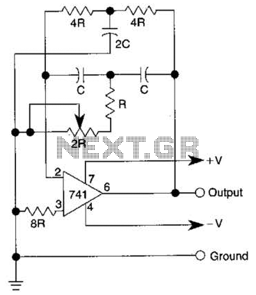
The quality of the sine wave depends on how closely the components in the twin-T network are matched in the operational amplifier's feedback loop. The twin-T network is a type of filter circuit commonly used in audio applications, signal processing,...
You can play this game alone or with your friends. The circuit comprises a timer IC, two decade counters and a display driver along with a 7-segment display. The game is simple. As stated above, it is a scoring...
In this fire alarm circuit, a thermistor functions as the heat sensor. As the temperature rises, its resistance diminishes, and conversely, when the temperature falls, its resistance increases. At standard temperature, the resistance of the thermistor (TH1) is approximately...
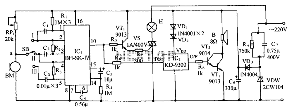
The circuit includes a microphone transducer, voice circuits, an SCR control circuit, a vocal music buck rectifier circuit, and an AC circuit. The BH-SK-IV serves as the core of the device. The described circuit is a complex assembly designed to...