
Dual-tone car horn
The circuit utilizes an LM556 dual timer integrated circuit, which is a versatile device that combines two independent timing circuits in a single package. In this configuration, U1 operates as a two-tone oscillator, generating two distinct audio frequencies that can be adjusted by modifying the capacitor values C2 and C3. The first oscillator, utilizing pins 1 through 6, produces an upper frequency signal of approximately 200 Hz, while the second oscillator, using pins 8 through 13, generates a lower frequency signal of about 140 Hz.
The output from the LM556 is taken from pins 9 and 5, which are connected to potentiometers that allow for manual adjustment of volume and balance control. This feature enables users to tailor the audio output to their preference, enhancing the overall listening experience. The dual 4-watt amplifier, U2, is designed to amplify the signals from the LM556, with each amplifier section delivering up to 4 watts of power to drive speakers with an impedance of 8 ohms.
The design ensures that the two-tone audio output can be effectively utilized in various applications, including sound effects, alerts, or musical tones. The circuit's flexibility in frequency adjustment and amplification makes it suitable for a wide range of electronic projects, from hobbyist applications to more complex audio systems. Proper power supply considerations and component ratings should be adhered to in order to ensure reliable operation and prevent damage to the components. An LM556 dual oscillator/timer, U1, configured as a two-tone oscillator drives U2, a dual 4-watt amplifier. One of the oscillators, pins 1 to 6, contained in U1 produces the upper frequency signal of about 200 Hz, while the second oscillator, pins 8 to 13, provides the lower frequency signal of about 140Hz.
Increase or decrease the frequencies by changing the values of C2 and C3. U1's outputs, pins 9 and 5, are connected to separate potentiometers to provide control over volume and balance. Each half of U2 produces 4W of audio that is delivered to two 8 ohms 🔗 External reference
Related Circuits
A new member has joined the forum and is seeking assistance with electronics, particularly from a technical engineering perspective, although they have some experience with circuits and schematics. The individual is likely looking to enhance their understanding of electronic components,...
This circuit diagram represents a radio-controlled system, commonly utilized in toy car applications for children. The circuit comprises two main components: the transmitter and the receiver circuits. The transmitter circuit generates radio signals through an oscillator circuit built with...
LEDs lining the headliner will fade in when the door is opened and fade out when the door is closed. The necessary components include a circuit to utilize 12V power from the vehicle to illuminate 15 LEDs and control...
The output of this circuit will be activated when a mix of two tones or frequencies is detected at the input. The frequency, denoted as f, is determined by the values of resistor R1 and additional components. This circuit is...
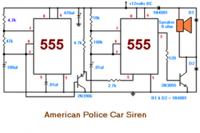
The second circuit simulates the siren of an American police car. It utilizes two 555 timers. The 555 timer on the right is configured as an alarm tone generator, while the second 555 timer on the left operates as...
Gates U1-a and U1-b of the 4093 quad 2-input NAND Schmitt trigger are connected in variable, low-frequency square-wave oscillator circuits. The output of gate U1-a is connected to one of the inputs of gate U1-b. The square-wave output of...