
Digital delay circuit lamp circuit 3
The described delay lamp circuit is a practical solution for bedside lighting, enabling users to control the light with ease and convenience. The bistable trigger switch configuration allows for reliable operation, ensuring that the light can be turned on or off with a simple press of the button. The inverter's role is critical in maintaining the state of the light, effectively managing the delay function through the integration of resistors and capacitors.
The adjustable delay time feature is particularly beneficial, as it allows users to customize the duration for which the light remains on after being activated. This is achieved by varying the resistance values in the circuit, which directly influences the time constant defined by the RC time constant formula. The stability of the circuit is further enhanced by the use of a rectifier circuit, which converts the AC input to a stable DC output, ensuring consistent performance regardless of fluctuations in the power supply.
In terms of component selection, the use of a 9013 NPN transistor as the driving element for the thyristor is a common practice, as it provides adequate current handling and switching capabilities. The choice of a bidirectional thyristor (M/C9.1A4) allows for effective zero-crossing triggering, reducing electrical noise and improving the overall reliability of the circuit.
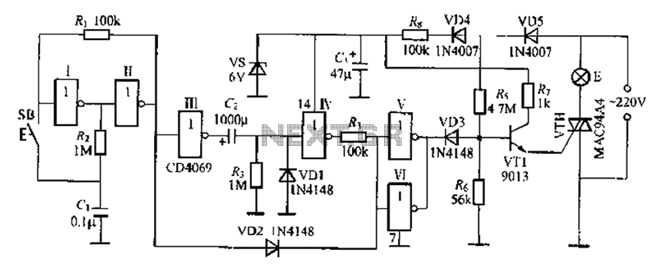
The design's simplicity, coupled with the effectiveness of the delay functionality, makes this circuit suitable for a variety of applications beyond bedside lighting, including decorative lighting and automated control systems where delayed activation is desired. The overall implementation of this delay lamp circuit exemplifies a well-thought-out approach to enhancing user experience through electronic design.A feast with enough delay lamp circuit is very suitable for use on the bedside table, which is characterized by a button SB, lights; then click the lights off; If the lights do not press the SB, the circuit is a delay time between after lantern [1 move off; if the lights go off before the connection resistance at the switch, Chan will fork up again. There r This lamp lights can delay canthus life easier, more pleasurable. Figure, an inverter [, and R-, R, and SB constitute bistable trigger switch, every time you press Ji Guan SB, inverter input H {ended level on the change again.
R., C, VD1 inverter I, composition t single steady-state delay circuit, adjusting column R. Or (1: Delay time can change the value of an inverter circuit V, f parallel use, to increase their ability to drive a diode VT1 and peripheral resistors VTH thyristor zero-crossing trigger. Mackerels road .220V AC power resistor R. buck, diode VD4, VD5 rectifier, vs stable regulated output voltage DC 6V, use for the entire circuit.
VT1 suitably 9013 type and other silicon NPN transistor, p ] .VTH available M/C9.1A4 type delete other small plastic bite bidirectional thyristor .SB for small touch switch. no special requirements other components. Q. the delay circuit theory by formula T O. 693RsC, seek, but because there are G chanting electrical factors, delay time will be increased to 30-SOmin and small.
Related Circuits
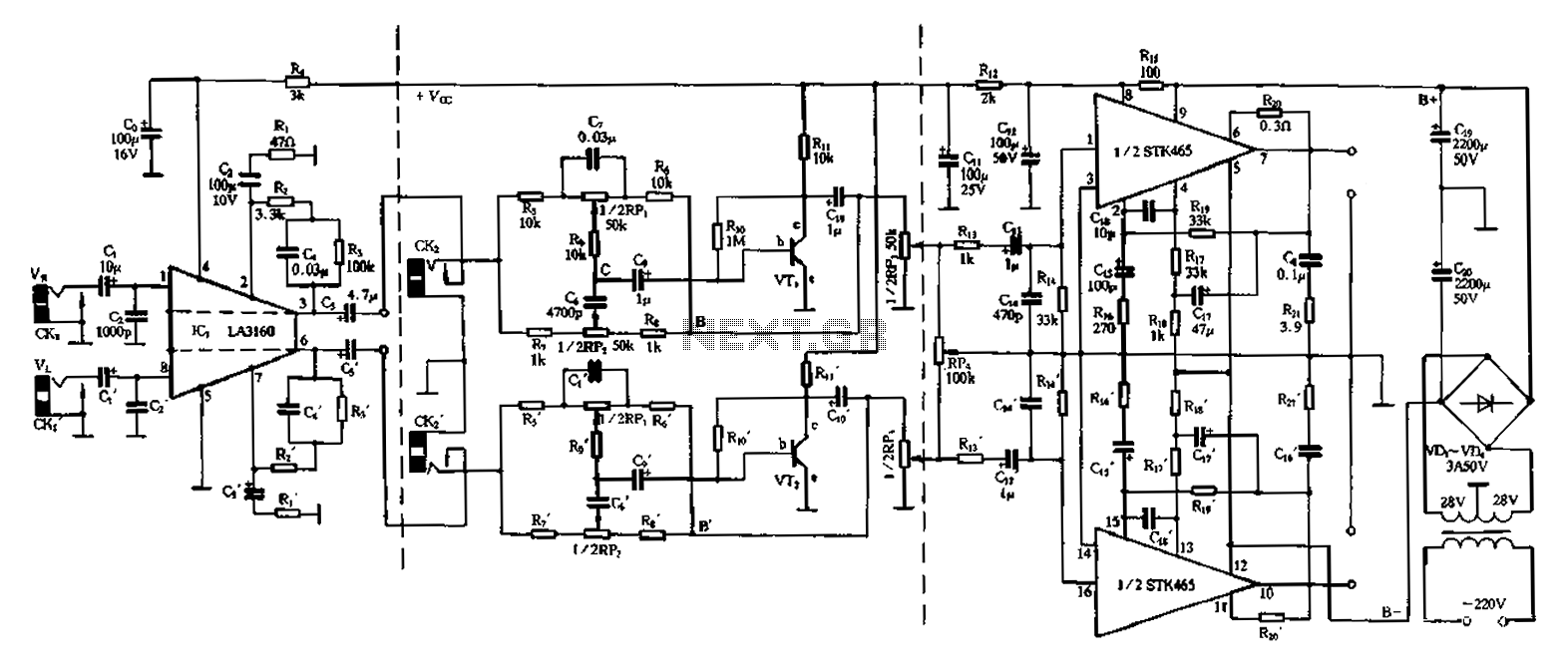
The 50W is a two-channel amplifier featuring a preamplifier and tone control based on the LA3160 integrated circuit. Its external components include the input preamplifier, with C1 serving as the input coupling capacitor. The circuit incorporates a high-frequency bypass...
This circuit is designed for dimming devices powered by transformer-based power supplies, specifically those operating at 12, 24, or 48 volts, rather than standard 120 volts. The project involves various components, including a soldering iron, wire strippers, breadboard or...
The basic two-transistor flasher has become widely utilized in various applications due to its simplicity and versatility. It has been employed in circuits such as a micropower low battery indicator, a lightning detector, an off-line switching power supply, a...
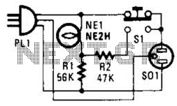
If residing in a cold climate, it is reassuring to confirm the functionality of an engine-block heater. This device indicates whether the heater is operational. To use, connect PL1 to a power outlet; the NE1 indicator should illuminate. Next,...

The intelligent control circuit for the iron is presented. This circuit utilizes the integrated circuit PT8A351X to manage functions such as direction detection, relay control, and LED indication. When the iron is positioned horizontally, it will power off after...

Various types of amplifiers include power amplifiers, audio amplifiers, tube amplifiers, stereo amplifiers, sensor amplifiers, RF amplifiers, sound amplifiers, and video amplifiers. Amplifiers are critical components in electronic circuits, serving to increase the amplitude of signals. Each type of amplifier...
Warning: include(partials/cookie-banner.php): Failed to open stream: Permission denied in /var/www/html/nextgr/view-circuit.php on line 713
Warning: include(): Failed opening 'partials/cookie-banner.php' for inclusion (include_path='.:/usr/share/php') in /var/www/html/nextgr/view-circuit.php on line 713