
144MHz Radio Beacon Circuit

The 2-meter transmitter circuit typically includes several key components to ensure efficient operation and signal clarity. At its core, the transmitter utilizes a stable oscillator, often based on a crystal oscillator circuit, which provides a precise frequency output at 144 MHz. This oscillator is crucial for maintaining the integrity of the signal being transmitted.
The output from the oscillator is then fed into an amplifier stage, which increases the power of the signal to ensure it can be transmitted over long distances. Commonly, a Class A or Class AB amplifier configuration is used to achieve a good balance between linearity and efficiency. Transistors or RF power amplifiers are typically employed in this stage to handle the required power levels.
To further enhance the performance, a low-pass filter may be integrated into the circuit to eliminate unwanted harmonics and spurious emissions, ensuring that the transmitted signal remains clean and within the regulatory limits. This filtering is essential for compliance with amateur radio regulations and to minimize interference with other communication services.
The power supply for the transmitter must be stable and capable of delivering the necessary voltage and current to all components, particularly during transmission bursts. Voltage regulators may be included to provide a consistent supply voltage across various operating conditions.
In addition to the transmitter circuitry, an antenna matching network is often included to optimize the power transfer between the transmitter and the antenna. This network ensures that the maximum amount of power is radiated by the antenna, thereby enhancing the overall range and effectiveness of the beacon.
Finally, a microcontroller or timer circuit may be employed to control the transmission intervals, allowing the beacon to operate automatically and efficiently. This feature is particularly useful for radio amateurs who use the beacon for testing equipment or providing location information.
Overall, the design of a 2-meter transmitter for amateur radio use as a beacon emphasizes signal quality, power efficiency, and regulatory compliance, making it a valuable tool for communication enthusiasts.The transmitter on 2 meters 144 MHz was designed mainly for use by radio amateurs as radio beacon and to this end, it produces a signal of good quality and.. 🔗 External reference
Related Circuits
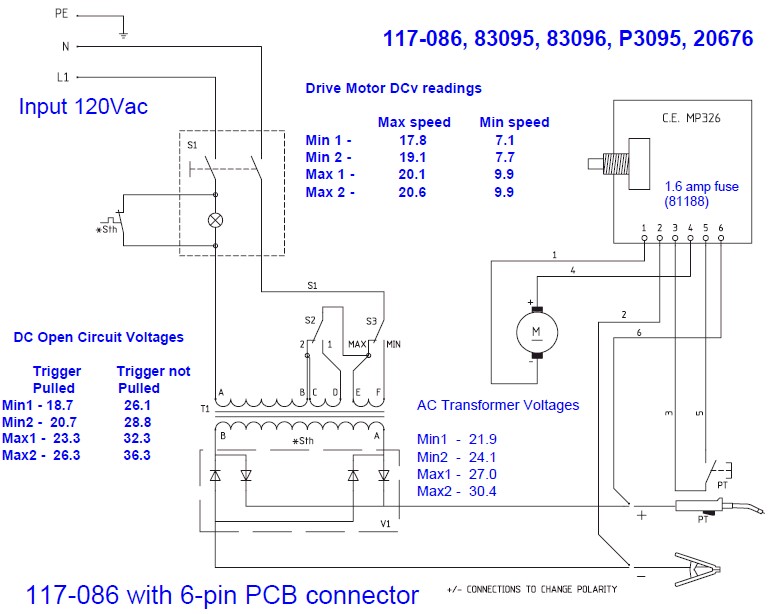
The wire speed DC motor consistently receives approximately 20 volts, irrespective of the switch position on the nozzle handle. The switch has been tested with an ohmmeter and functions properly. Even after disconnecting the switch from the circuit board,...
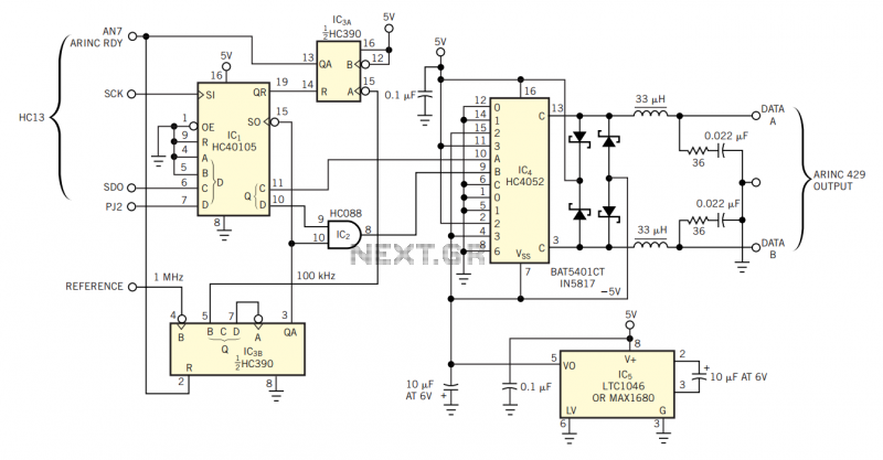
The physical transmission medium for the 429 standard is 78Ω shielded, twisted-pair cable that uses a complementary, differential bipolar RZ (return-to-zero) waveform. The voltages are the net differentials that the biphase drive develops: For example, the differential is 10V...
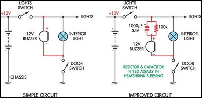
Two headlight reminder circuits are designed for easy installation and operation based on the KISS (Keep It Simple Stupid) principle. The basic circuit consists of a 12V piezo buzzer connected between the lights circuit and a door switch. The...

An ultra-low-noise, low-distortion operational amplifier, the AD797, is combined with the ADS 11 operational amplifier, which provides high bandwidth and a 100-mA output drive capability. This composite amplifier circuit is effective for driving high-resolution ADCs and ATE systems. The...
A simple test circuit designed for troubleshooting audio and radio equipment. It can inject a square wave signal rich in harmonics or be used with headphones as an audio tracer. A single-pole double-throw switch is utilized to toggle between...
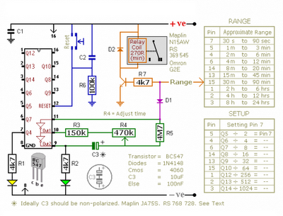
The CMOS 4060 is a 14-bit binary counter; however, only ten of these bits are connected to output pins. The 4060 also includes two inverters, which are connected in series across pins 11, 10, and 9. Together with resistors...