
PC controls light dimmer

The described circuit utilizes a low-power digital-to-analog (D/A) converter as its core component, which is responsible for converting digital signals from a computer's parallel port into corresponding analog voltage levels. This conversion allows for precise control of the light intensity, making it suitable for various applications in both residential and professional environments.
The isolation between the low-voltage DC components and the high-voltage AC components is achieved through an optoisolator. This device ensures that there is no direct electrical connection, thereby enhancing safety and preventing potential damage to the low-voltage circuitry. The optoisolator is tasked with triggering a triac (T1), which functions as a switch controlling the AC supply to the lamps. The operation of the triac is based on the phase control method, where the timing of the trigger signal determines how long the triac remains conductive during each AC cycle.
As the triac is triggered earlier in the AC cycle, it allows more current to flow to the load, thereby increasing the intensity of the lamps. The D/A converter's output voltage directly influences this triggering point. The DAC is buffered to ensure it can supply sufficient current to the optoisolator, allowing for reliable operation. A reference voltage of 2.5V is generated by an integrated circuit (IC3), which serves as a stable reference for the D/A converter's output.
Timing characteristics of the D/A converter are established by a crystal oscillator along with capacitors (C1 to C4), ensuring accurate and stable operation. The DAC1220 model from Burr-Brown is utilized for this application, interfacing with the computer's parallel port through a three-wire serial connection for the transfer of digital codes.
User interaction is facilitated through a Pascal program that reads keyboard inputs. Specific keys (Q and W) allow users to increment or decrement the digital code sent to the D/A converter, thus adjusting the lamp's brightness. Upon system initialization, the D/A converter is set to a digital code of zero, corresponding to the reference voltage output of 2.5V, effectively turning the lamp to a half-on state. Users can subsequently fine-tune the light intensity to their preference using the keyboard.
The entire DC portion of the circuit is designed to operate with minimal power consumption, approximately 5 mA, which contributes to the overall efficiency of the system. This circuit exemplifies a practical application of digital control in lighting systems, combining safety, efficiency, and user-friendly operation.Using the simple circuit in Figure 1, you can control the light intensity in your room or work area from your PC. The heart of the circuit is a low-power D/A converter that converts digital words from a computer's parallel port to analog-voltage signals.
To isolate the dc low-voltage part of the circuit from the high-voltage part, the circuit uses an optoisolator, which prevents any direct electrical connection between the two sections. The optoisolator triggers triac T1, which behaves like a switch. In each power cycle, T1 switches on, the ac supply voltage connects to the load (lamps), and current starts flowing in the triac.
At the end of a half-period, when the current drops to zero, T1 turns off and awaits another trigger in the opposite direction. This additional trigger occurs in the second half-period of the power cycle. A lower triggering voltage makes T1 conduct at an earlier point in and stay on for a larger fraction of the cycle.
The larger fraction corresponds with transferring more power to the lamp, resulting in a higher intensity.
The output voltage of the D/A converter sets the triggering point. The DAC, after one stage of buffering, provides enough current to drive the optoisolator. IC3 generates a 2.5V reference; the crystal oscillator and capacitors C1 through C4 set the DAC's timing characteristics. The DAC1220 (Burr-Brown Corp, www.burr-brown.com) connects to the parallel port with three wires for serial transfer of the digital codes.
The Pascal program of Listing 1 reads the PC's keyboard; when you press Q or W, the routine increments or decrements a digital code and sends it to the DAC. The DAC then controls the lamp's intensity. Upon power-up, the DAC receives a digital code of zero, which corresponds to a 2.5V output (the reference voltage).
You then adjust potentiometer R3 such that the lamp is half on. Using the keyboard, you can change the light intensity to the desired level. The dc part of the circuit consumes only approximately 5 mA.
Related Circuits
A light/dark sensing circuit is highly useful and versatile for various renewable energy projects, including automatic lighting and security systems. The article on Light Dependent Resistors (LDR) explains how an LDR can be employed in simple circuits to control...
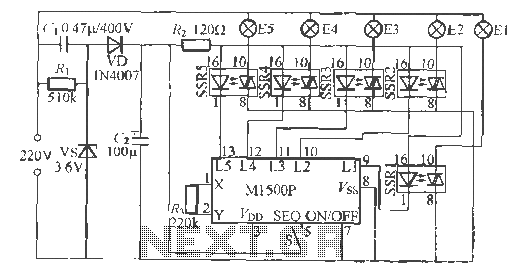
The Shenzhen Skywave Semiconductor Co., Ltd. produces a five-flash integrated circuit controller known as M1500P. This device is manufactured using a DIP 14 standard package and can be customized according to customer specifications for soft seal packaging. It operates...
Chandelier Dimmer. Many chandeliers are equipped with a pull cord switch. Enhance your chandelier with a unique feature to surprise your guests by integrating a small wire down the lamps. The chandelier dimmer circuit allows for the adjustment of light...
This circuit is similar to the previous one but incorporates a photoresistor to trigger the flip-flop instead of a push button. A bias resistor is placed in series with the photoresistor to ensure that adequate voltage is present at...
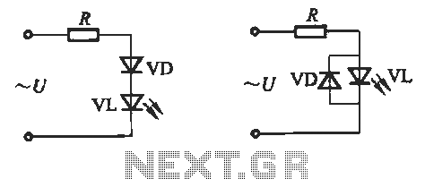
Light-emitting diodes (LEDs) can be powered using direct current (DC), alternating current (AC), and pulse drivers. A typical buck LED display circuit is illustrated in Figure 13-1. The current-limiting resistor (R) for LED tubes can be calculated using the...
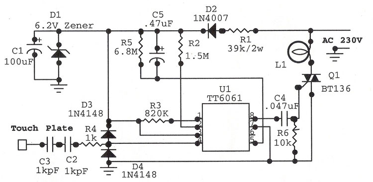
This circuit is a touch-sensitive lamp delay switch characterized by minimal static power consumption. It utilizes an external switch terminal, which can directly replace a standard switch. The circuit features a novel precision voltage regulator integrated circuit, such as...