
Car Controller using PIC16F870
Since each of these modules does a specific job, the system can be expanded and enhanced by creating new modules with (hopefully) little or no changes to existing ones.
Each is powered by 12 volts DC and has a network connection.
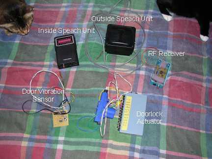
The entire system is orchestrated from the control Console Unit (velcrod to the top of the dashboard). The front panel has a 2 line by 8 character LCD display, momentary push button, and rotary encoder.
The rear panel has the 12 volt power connector, network RCA jack, daylight sensor (solar cell from old calculator), and 5-pin din connected to directly reprogram the internal PIC without opening the case. Pulling the power and network connections, the unit can be hauled into the shop for easy reprogramming. Or, using a laptop computer, can be reprogrammed while still mounted in the car.
Both the front and back panels of the project box have been replaced with Lexan. Unlike the older type of Plexiglass, you can just drill, cut, and generally mangle this material without it shattering.
Development and Debug -
From previous experience doing network style designs, it was decided to do all communications in ASCII. This allows individual units to be debugged using a PC terminal program. It also allows the entire system's network traffic to be monitored and logged. An interface device using a PIC12F675 was constructed to convert the RS-232 serial from the computer to the speed independent, open collector, network signals.
The proposed car controller system utilizes a modular design approach, featuring multiple microcontroller units (MCUs) networked to enhance functionality and simplify future expansions. The initial controller is based on the PIC16F870 microcontroller, which manages essential functions such as remote door locking, headlight reminders, and car location tracking. The wire-wrap construction allows for straightforward modifications, although it introduces challenges for maintenance and upgrades.
Each microcontroller module operates on a 12V DC power supply and is interconnected through a network interface, facilitating communication between units. This design supports scalability, enabling the addition of new modules without significant alterations to existing components. The control Console Unit, affixed to the dashboard, serves as the central hub for user interaction, equipped with a 2x8 character LCD for display, a momentary push button for manual inputs, and a rotary encoder for navigation through options.
The rear panel of the Console Unit includes essential connectivity features such as a 12V power connector, an RCA jack for network connections, and a daylight sensor sourced from an obsolete calculator. A 5-pin DIN connector is incorporated for direct reprogramming of the PIC microcontroller, allowing for easy updates either in the vehicle or in a workshop setting.
The use of Lexan for the project box panels enhances durability, permitting modifications without the risk of shattering, unlike traditional Plexiglass. The communication protocol is designed in ASCII format, enabling effective debugging and logging of network traffic through a PC terminal program. An interface device utilizing the PIC12F675 converts RS-232 serial signals to a speed-independent, open collector format, ensuring compatibility across the networked modules. This comprehensive design aims to streamline vehicle control systems while providing flexibility for future enhancements.Our present car controller runs on a single PIC16F870 micro and provides functions for remote door locks, headlight reminder, and car finder. It is constructed using wire-wrap to allow for future expansion and is mounted using Velcro on the passenger side of the center console.
The downside of this design is that changes to the system require a lot of work for removal, rewiring, reprogramming, and reinstalling. It could also be stolen which would be a major bummer - making something the first time is interesting, having to do it all over is not.
The idea it to replace this with a set of microcontroller modules networked together. Several of these modules have already been constructed on single-sided circuit boards (see how we do this). Since each of these modules does a specific job, the system can be expanded and enhanced by creating new modules with (hopefully) little or no changes to existing ones.
Each is powered by 12 volts DC and has a network connection. The entire system is orchestrated from the control Console Unit (velcrod to the top of the dash board). The front panel has a 2 line by 8 character LCD display, momentary push button, and rotary encoder. The rear panel has the 12 volt power connector, network RCA jack, daylight sensor (solar cell from old calculator), and 5-pin din connected to directly reprogram the internal PIC without opening the case.
Pulling the power and network connections, the unit can be hauled into the shop for easy reprogramming. Or, using a laptop computer, can be reprogrammed while still mounted in the car. Both the front and back panels of the project box have been replaced with Lexan. Unlike the older type of Plexiglass, you can just drill, cut, and generally mangle this material without it shattering.
Development and Debug - From previous experience doing network style designs, it was decided to do all communications in ASCII. This allows individual units to be debugged using a PC terminal program. It also allows the entire system's network traffic to be monitored and logged. An interface device using a PIC12F675 was constructed to convert the RS-232 serial from the computer to the speed independent, open collector, network signals.
🔗 External reference
Related Circuits
This is a switching circuit that provides a latching mechanism to create a set of radio buttons using push buttons. This circuit consists of an interlocking circuit. The switching circuit operates on the principle of latching, allowing multiple push buttons...
A digital integrated circuit simplifies the response process significantly. The diagram illustrates a circuit comprising four responder groups. The digital integrated circuit described serves as a crucial component in various electronic systems, primarily focusing on enhancing response efficiency. It comprises...
Every innovation begins with a simple everyday problem, such as watching an IPL match on TV when suddenly the power goes out, prompting the search for an alternative way to watch via mobile network. Similarly, a frequent issue of...
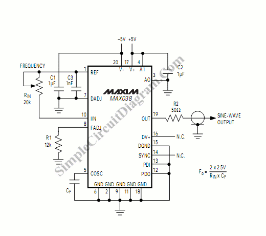
A function generator that operates within a frequency range of 0.1 Hz to 20 MHz can be easily constructed using the MAX038 integrated circuit chip. This describes a straightforward implementation of the device. The MAX038 is a precision waveform generator...
The circuit utilizes a Bute CD12V Lee power MOSFET transistor (BU1RF744) that operates in a switching mode, turning on and off repeatedly. The output voltage is influenced by the characteristics of the MOSFET, which is designed for efficient performance....
V_logic is connected to the power supply Vs and all ground are connected to the negative terminal of the battery. Fout is a square wave of varying frequency with a maximum amplitude of Vs. A voltage divider is needed...