
FM Electrocardiogram Monitor with LM331/LM231
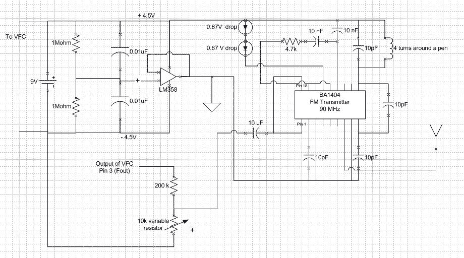
The circuit described operates with a logic voltage (V_logic) connected to a power supply (Vs), while grounding is established through the negative terminal of a battery. The output frequency (Fout) is a square wave, varying in frequency with a maximum amplitude equivalent to Vs. A voltage divider composed of a 200kΩ resistor and a 10kΩ variable resistor in series is utilized at pin 3 to attenuate the voltage to a range of 20-50 mV, suitable for subsequent processing.
The source-splitting amplifier is designed to provide three reference potentials: +4.5V, -4.5V, and ground. Given that the BA1404 integrated circuit operates with a maximum supply voltage of +3V, two diodes are employed to create a voltage drop of 1.4V, ensuring proper functionality of the transmitter. The entire circuit can be powered with a single 9V battery, enhancing its portability.
The input signal to the transmitter is critical, requiring levels in the millivolt range (5-50 mV). The inclusion of a variable voltage divider at the input stage is essential for optimal performance. Notably, this configuration negates the need for additional DC offset circuitry to adjust the ECG output signal from the amplifier. The voltage follower circuit (VFC) operates within a range of -4.5V to +4.5V, providing an inherent offset that allows it to process ECG signals centered around 0V, with swings of -0.5V to +0.5V translating to a 3.5V to 4.5V input range.
Creating an inductor for the tunable FM transmitter is a meticulous task; however, experimentation has shown that winding a wire four times around a pen can successfully transmit signals at a frequency of 90 MHz. The circuit includes a summing amplifier with unity gain, cascaded with an inverting amplifier configured for a gain of approximately two. The summing amplifier combines the input from the FM radio receiver (tuned to around 90 MHz) with a constant voltage derived from another voltage divider. The resulting signal is then processed by the inverting amplifier, which amplifies and inverts the signal.
This amplification is crucial as the FVC (LM231) requires a minimum peak-to-peak amplitude of 2V for proper operation. The incoming signal from the radio receiver typically exhibits a peak-to-peak amplitude of around 500 mV. While increasing the volume can enhance the signal amplitude, it may also lead to a reduction in the signal-to-noise ratio (SNR). The designed amplifier at the receiving end effectively boosts the signal to at least 5V peak-to-peak, ensuring it meets the requirements for FVC conversion.V_logic is connected to the power supply Vs and all ground are connected to the negative terminal of the battery. Fout is a square wave of varying frequency with a maximum amplitude of Vs. A voltage divider is needed (200k and 10k variable resistor connected in series) is needed at pin 3 to scale the voltage down to around 20 -50 mV.
The source-splitting amplifier allows three different potential reference: + 4.5V, -4.5V and Ground. Since the BA1404 can only have +3V as its power supply, we used two diodes to create a total drop of 1.4V and this allows the transmitter to function properly. Another advantage to this setup is that every elements on this circuit can be powered off a signal 9V battery.
Although not noted on this schematics, one should know that the input to the transmitter should be on the order of mV (5 - 50mV). Implementing a variable voltage divider to the input is very important. The nice thing about this setup is that one does not need an DC offset circuitry to adjust ECG signal from the output of the amplifier. Since our VFC is powered between -4.5V and +4.5V, it has a 4.5V offset already. If the ECG signal is centered at 0V with a swing from -0.5 to +0.5V, then the VFC sees it as 3.5V to 4.5V swing.
It is important to know that VFC cannot have negative voltage as its input. Furthermore, making an inductor at the tunable FM transmitter range is a painstaking process. We found that by turning a wire 4 times around the pen allows the signal to be transmitted at 90 MHz. This section consists os a summing amplifier with a gain of one cascaded with an inverting amplifier with a gain of approximately two.
The summer takes the input obtained from the receiver (a FM radio tuned at approximately 90 MHz) and adds it to a constant voltage obtained using a simple voltage divider. This signal is then sent to an inverting amplifier which provides a gain of two and inverts the signal after it has been inverted by the summing amplifier.
The reason we amplified the signal is due to the fact that FVC (LM231) needs at least a 2V peak-to-peak amplitude. The signal coming from the radio receiver has a peak-to-peak amplitude around 500 mV. Increasing the volume will normally increase the signal amplitude but it will also decrease the signal-to-noise (SNR) ratio.
The amplifier we designed at the receiving end increase the signal to at least 5V of peak-to-peak amplitude, which is sufficient for FVC conversion. 🔗 External reference
Related Circuits
This is a straightforward schematic of an amplifier and filter. The circuit primarily features an LM124 operational amplifier configured in an inverting setup. The schematic illustrates a basic audio amplifier and filter circuit utilizing the LM124 operational amplifier. The LM124...
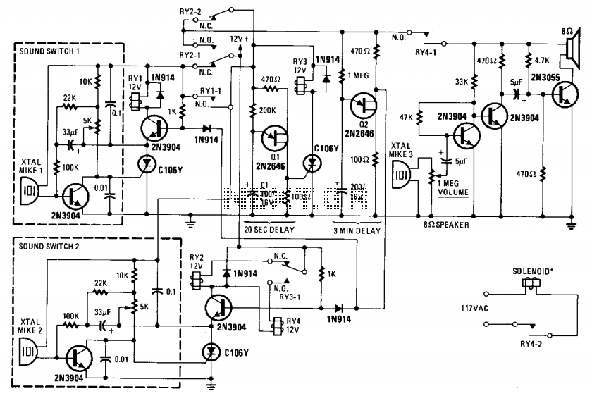
This device monitors sounds in a home or office when a telephone is called from a remote location. The described device functions as an audio monitoring system that activates upon receiving a telephone call. The core of this system typically...
As shown in the figure, D187 is a UART with its RX/TX signals connected through optocouplers N21, N22, and N29, providing complete optoelectronic isolation for the RS-485 communication interface receiver/transmitter D28 and microprocessor D211. D197 serves as a generator,...
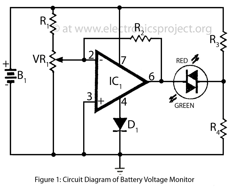
Battery voltage monitor is utilized to indicate the voltage level of a 12-volt battery circuit, specifically in a verified electronics project circuit. The battery voltage monitor circuit is designed to provide a visual representation of the voltage level of a 12-volt...
This discussion assists in selecting the most appropriate microprocessor supervisor integrated circuit (IC) for specific applications and provides solutions for various common supervisory issues encountered with microprocessors. Microprocessor supervisor ICs are critical components in ensuring the reliable operation of microprocessor-based...
Observing and addressing the phase adjustment issues in electric transmission lines manually poses significant challenges, particularly in recording and normalizing three major problems. This design encompasses both software and hardware components, developed over an extended period. It is intended...