
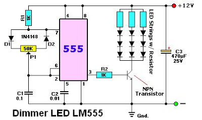
Intermittent ozone generator circuit diagram using NE555
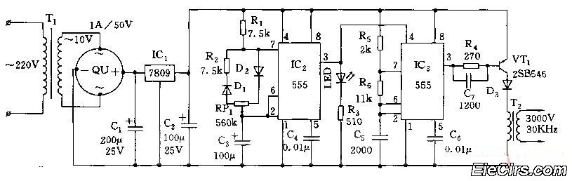
The circuit utilizes an adjustable resistor, RP1, to fine-tune the pulse duty cycle generated by integrated circuit IC2. This pulse duty cycle is critical as it directly influences the output pulse oscillation time of another integrated circuit, IC3. The oscillation time is a key factor in determining how long the ozone generator operates, which in turn affects the concentration of ozone produced in the air.
In practical terms, the adjustment of RP1 modifies the on-off duration of the pulses emitted by IC2. A higher duty cycle results in a longer 'on' time, increasing the operating time of the ozone generator, which leads to a higher concentration of ozone. Conversely, a lower duty cycle reduces the operating time, thus decreasing the ozone concentration.
This configuration is particularly useful in applications where precise control of ozone levels is necessary, such as in air purification systems or industrial processes that require specific ozone concentrations for optimal performance. The ability to adjust the duty cycle allows for flexibility in response to varying environmental conditions or specific operational requirements.
In summary, the circuit's design effectively enables the user to manipulate ozone generation through careful adjustment of the pulse duty cycle, ensuring that the desired air quality standards can be met consistently.Adjust the RP1, adjustable the IC2 pulse duty cycle to change IC3 pulse oscillation time, to regulate the the ozone generation time, thus achieving the purpose of changing the concentration of ozone in the air. 🔗 External reference
Related Circuits
The objective is to design a square-wave generator with an output range of 0 to +5V. Additionally, the design should allow for the modification of the signal to enable adjustment of the duty cycle of the pulse (PWM). The square-wave...
This rain sound effects generator circuit simulates the sound of rain and can be utilized in electronic music and radio shows. The noise source employs a germanium diode that is directly polarized and subsequently amplified by a single-stage amplifier...
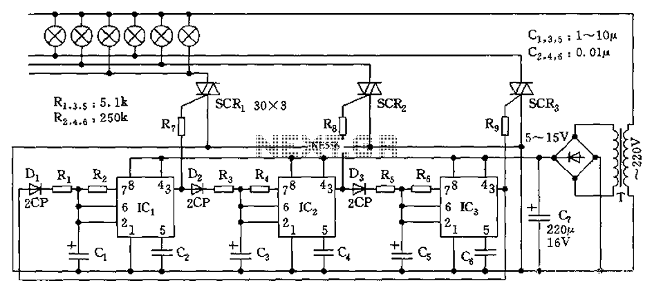
The circuit utilizes a 555 timer as its core component to control three lights through a cyclic trigger monostable delay circuit. The brightest light is controlled by a silicon-controlled rectifier (SCR) that determines the cycle of illumination. When pin...
The LM555 timer IC can be utilized in various electronic projects, including the creation of an analog timer. According to the datasheet, the LM555 is versatile and can be adjusted to set timers based on specific requirements. The schematic...
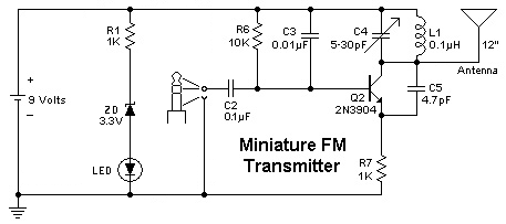
To replace a microphone with a 3.5" audio jack in a circuit, modifications will be necessary. The circuit currently utilizes an electret microphone, and adjustments must be made to accommodate the audio jack for audio transmission. The audio jack...
The figure illustrates an NE555 frequency modulation (FM) circuit. In this circuit, pin 7 of the NE555 is connected to an FM modulation section that consists of resistor R5 and capacitor C2, although the frequency range is somewhat limited....
Warning: include(partials/cookie-banner.php): Failed to open stream: Permission denied in /var/www/html/nextgr/view-circuit.php on line 713
Warning: include(): Failed opening 'partials/cookie-banner.php' for inclusion (include_path='.:/usr/share/php') in /var/www/html/nextgr/view-circuit.php on line 713