
Dunlop Cry Baby Wah Wah Schematic

The Dunlop Cry Baby Wah Wah pedal is renowned for its distinctive tonal qualities and is a staple in many guitarists' setups. The schematic of this pedal showcases the various components that contribute to its iconic sound. The circuit typically includes a potentiometer, which controls the wah effect by varying the resistance and, consequently, the frequency response of the signal.
The heart of the Cry Baby circuit often involves an operational amplifier configured as a bandpass filter. This allows the pedal to accentuate certain frequencies while attenuating others, creating the signature "wah" sound that is sought after in many musical genres. The circuit may also incorporate additional components such as capacitors and resistors to shape the frequency response further and ensure stability in operation.
Moreover, the Cry Baby Wah Wah pedal may utilize a bypass switch to allow the guitarist to toggle between the effect being engaged and a true bypass mode, ensuring that the original tone of the instrument is preserved when the effect is not in use. The overall design emphasizes simplicity and effectiveness, making it a preferred choice for both amateur and professional musicians.
Understanding the schematic layout, including the placement of each component and their interconnections, is crucial for anyone looking to repair, modify, or build a similar wah pedal. The unique characteristics of the Dunlop Cry Baby Wah Wah, combined with its straightforward circuit design, make it an enduring favorite in the world of electric guitar effects.Dunlop Cry Baby Wah Wah Schematic Still its hard to be the Cry Baby sound for what it is.. 🔗 External reference
Related Circuits
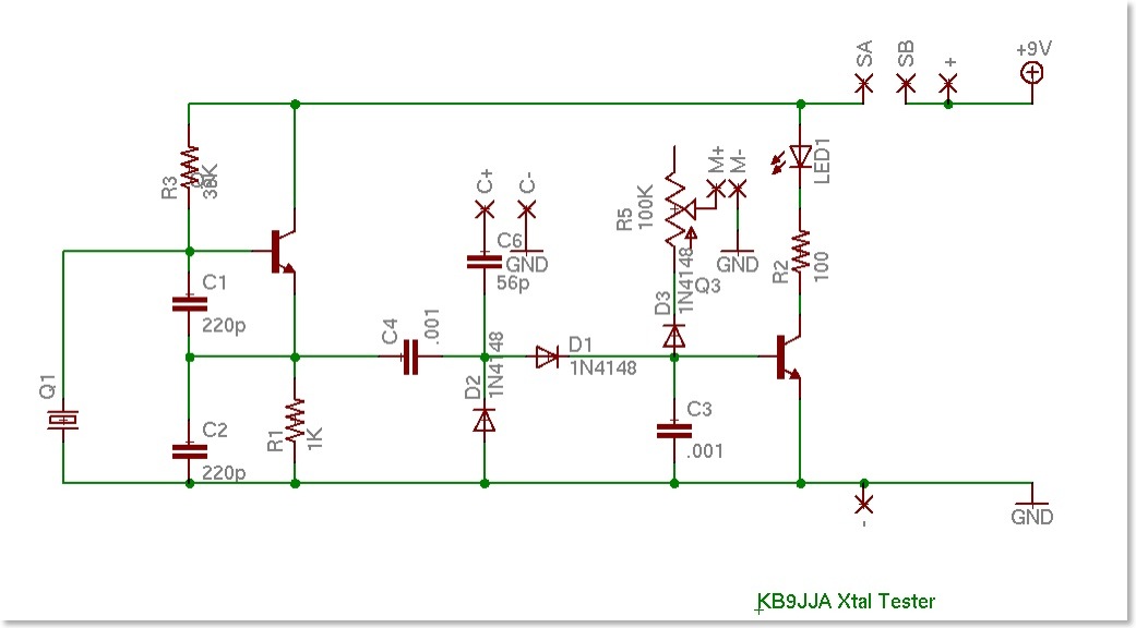
A crystal tester was developed to evaluate various crystals for a project. Existing testers available online were found to be lacking in certain features. Therefore, modifications were made to an existing design to incorporate desired functionalities, along with the...

Fluorescent lamps, despite their long presence, remain enigmatic to many individuals due to their complex operational mechanisms. The lamp consists of a gas mixture, primarily containing mercury, which, when energized as an arc, produces a significant amount of short-wave...
During the process of organizing computer files, a schematic was discovered that was utilized in the initial phase of USB LED Matrix development. It is believed that this schematic could be beneficial to others. The schematic in question pertains to...
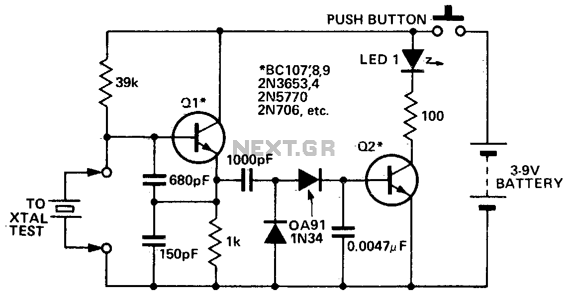
This circuit is designed to check fundamental oscillations. When Q2 conducts, the LED lights up. It operates with A3 HF crystals on a "Go-No-Go" basis. An untuned or 6V, 40mA bulb can be used in place of the Colpitts...
Electronic circuits are presented in schematic form. A schematic is essentially a map that illustrates the path of current through various components. Each component is represented by a symbol, typically accompanied by a label or a value, or both....
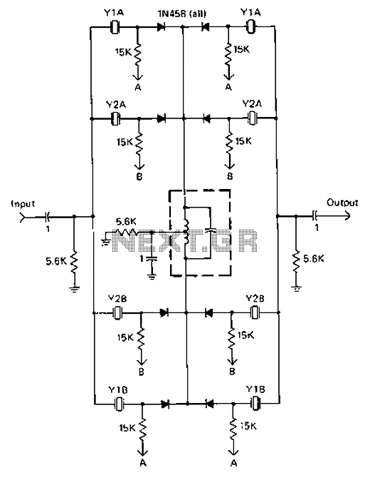
A 9-12V DC power supply is connected to control point A or point B for an amateur communication receiver IF amplifier, offering two distinct options. The power frequency is set at 455 kHz with a bandwidth of 500 Hz....