
Car Horn
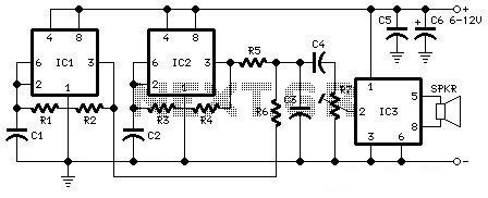
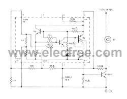
The car horn circuit schematic serves as a guide for automotive enthusiasts looking to modify or enhance their vehicle's horn system. The circuit consists of various resistors, capacitors, and a potentiometer, each playing a critical role in the operation of the horn.
The resistors, designated as R1, R2, R3, R4, R5, R6, and R7, are used to set the biasing conditions and control the current flow within the circuit. Resistor R1, with a value of 68K, helps in limiting the current to protect sensitive components. R2 at 2K2 and R3 at 56K are used for voltage division and signal conditioning, while R4 at 3K3 and the pair of R5 and R6 at 4K7 each help in controlling the overall gain of the circuit. R7, a 10K potentiometer, provides the ability to adjust the output level, allowing for customization of the horn's sound intensity.
The capacitors, labeled C1 through C6, are crucial for filtering and smoothing the signal. C1 and C2, both rated at 22nF, are used for high-frequency noise filtering, ensuring that the horn operates smoothly without unwanted interference. Capacitors C3 and C5, rated at 100nF, serve a similar purpose but are tailored for different sections of the circuit to stabilize voltage levels. C4, with a value of 1nF, is likely used for decoupling purposes, while C6, also at 22nF, may serve as a coupling capacitor to block DC voltage while allowing AC signals to pass through.
This schematic can be implemented as part of a broader modification project, enhancing the auditory signaling capabilities of a vehicle. Proper assembly and adherence to the specified component values are essential for optimal performance. Additionally, careful attention should be paid to the power supply requirements and the integration of this circuit with existing automotive systems to ensure reliable operation.The following diagram is the schematic diagram fo Car Horn, you may try this circuit for your car modification Components List: R1 = 68K R2 = 2K2 R3 = 56K R4 = 3K3 R5,R6 = 4K7 R7 = 10K Pot/trimpot C1,C2 = 22nF C3,C5 = 100nF C4 = 1nF C6 = 22.. 🔗 External reference
Related Circuits
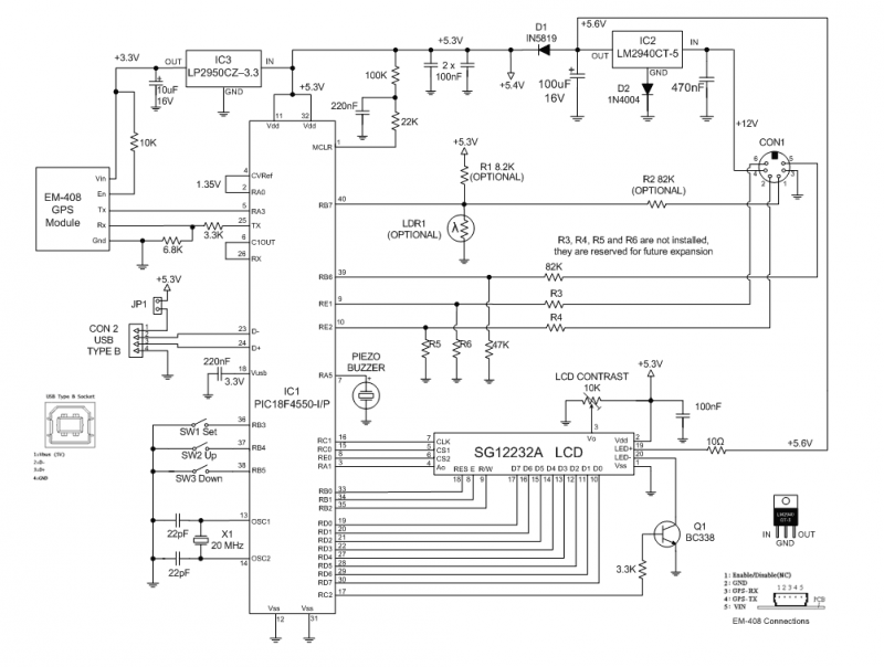
The GPS Car or Boat Computer is capable of displaying a variety of GPS-related information for enthusiasts of driving or boating. This page contains all the necessary information to construct the unit, including design specifications, schematic diagrams, parts list,...
What's so special about this circuit? Well, the first third-brake light I installed I had to pull a wire from the Third Brake Light all the way underneath the carpet to the brake-pedal-switch and I thought it would be...
How can a 1950 Studebaker be enhanced? By installing an iPod Nano in the dashboard. The team at MAYA Design created a touch-controlled sound system for this project, referred to as the "Nano-Baker" or "Stude-iPod," utilizing a pair of...
If you have ever used a 12V flasher relay system, typically a mechanical type, for general automotive applications, today we will attempt to build a 12V flasher relay circuit. The 12V flasher relay circuit is a crucial component in automotive...
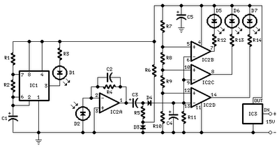
All distances mentioned can vary depending on the infrared transmitting and receiving LEDs used and are significantly affected by the color of the reflecting surface. Black surfaces greatly reduce the device's sensitivity. This circuit can also be applied in...
A simple but useful circuit for all who have problems with parking a car in spaces without good visibility. The electric circuit appears in picture 1. It is constituted by the IC1 and components around it. When the car...
Warning: include(partials/cookie-banner.php): Failed to open stream: Permission denied in /var/www/html/nextgr/view-circuit.php on line 713
Warning: include(): Failed opening 'partials/cookie-banner.php' for inclusion (include_path='.:/usr/share/php') in /var/www/html/nextgr/view-circuit.php on line 713