
Car lamp failure detector

The described circuit functions as a DC current sensing switch, operating within a voltage range of 8 to 16 volts. The critical component, R1, is selected to produce an output of approximately 100 mV at a specified trip current, effectively allowing the circuit to detect when the current exceeds this threshold. This voltage level serves as a reference for triggering the subsequent actions in the circuit.
In its application as a car lamp failure switch, the circuit monitors the current flowing to a cluster of up to four lamps, each rated equivalently. The resistor R is positioned in series with the wiring harness that supplies power to these lamps. When a lamp fails, the change in current flow is detected, and the circuit responds accordingly, activating the relay (RL1-2) to signal the failure condition.
The part list indicates various resistors (R1 through R14) with specific values, including several 10 kOhm resistors and a 2.2 kOhm resistor, which are commonly used for biasing and feedback in operational amplifier circuits. The operational amplifiers (IC1-2) utilized are LM741, which are standard components for such applications, providing necessary amplification and signal processing.
The circuit also includes diodes (D1-2, 1N4001), which are essential for protecting against reverse polarity and ensuring proper current flow direction. The use of trimmer potentiometers (RV1-2) allows for fine-tuning of resistance values, facilitating precise adjustments to the trip point of the current sensing function.
Transistors (Q1-2, BC214L) are incorporated for switching purposes, enabling the relay to be actuated based on the output from the operational amplifier. This design ensures that the circuit can reliably indicate lamp failures by activating the relay when the monitored current drops below the expected level due to a burned-out lamp.
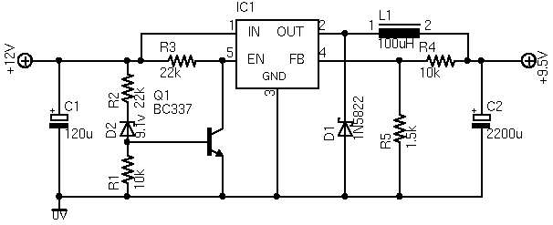
Overall, this schematic effectively combines various electronic components to create a robust current sensing and monitoring solution for automotive lighting systems, providing a practical application for enhancing vehicle safety through timely alerts for lamp failures.In Fig.1 see a DC current ? sensing switch, in which the current is applied from an 8 to 16 Volt supply. The R1 value is chosen so that it generates roughly 100 mV at the required trip current. In Fig. 2 shows how the above circuit can be made to act as a car lamp ? failure switch which turns on if any of the monitored lamps burn out. R is wired in series with the wiring harness feed to a selected ??cluster? of up to four similarly rated lamps. Part List R1-8=*See text R9-10-11-12=10Kohms RL1-2=12V >120R RELAY R2-3-4-5=10Kohms RV1-2=1Kohms trimmer IC1-2=LM741 R6-13=2.2Kohms D1-2=1N4001 LB1-4=12V lamp R7-14=4.7Kohms Q1-2=BC214L 🔗 External reference
Related Circuits

Illuminate your tabletop with this stylish White LED Lamp. It is powered through a USB port, making it perfect for taking notes while browsing the internet. The USB port can provide a convenient power source. The White LED Lamp is...
A single chip metal detector with a range of a few inches. This is useful for detecting nails or screws in walls and floors, or for locating buried mains cable. The single-chip metal detector circuit typically consists of a few...
The ASUS Eee is an exceptional ultra-portable notebook that includes nearly all the necessary features for technology enthusiasts while omitting unnecessary elements. Additionally, it boasts an impressive build quality. The ASUS Eee series is designed with portability and functionality in...
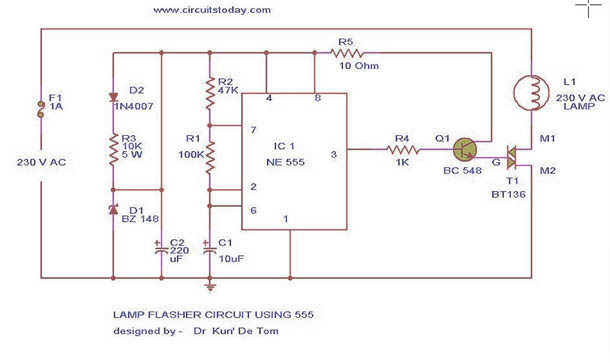
This circuit diagram represents a lamp flasher powered by mains electricity. It is capable of flashing lamps with a maximum power of 200 Watts at user-defined rates. The NE555 integrated circuit is configured as an astable multivibrator, generating the...

This amplifier is designed to be integrated with preamplifiers that lack a phono input. A phono input is essential for standard record players equipped with dynamic pick-ups, which remain widely used. The amplifier not only elevates the output of...
The metal detector circuit is shown here that the limits represent the sake of simplicity for a metal detector, but the design works remarkably well. It only uses 40,106 Hex Schmitt inverter IC, a capacitor and a search coil...