
Metal Detector

The single-chip metal detector circuit typically consists of a few essential components that work together to detect metallic objects. At its core, the circuit utilizes an oscillator, which generates an electromagnetic field. This electromagnetic field is emitted from a coil, often referred to as the search coil or antenna. When a metallic object, such as a nail or screw, enters this field, it induces eddy currents in the metal, which in turn alter the electromagnetic field.
The oscillation frequency of the circuit is usually within the range of a few kilohertz. The change in the electromagnetic field caused by the presence of metal is detected by the same coil or a separate sensing coil. This detection mechanism is often enhanced by using a microcontroller or dedicated IC that can process the signals received from the coil.
The circuit may include additional components such as resistors, capacitors, and diodes to filter and amplify the detected signal. A simple audio output device, like a buzzer or speaker, can be integrated to provide an audible indication when metal is detected. Furthermore, an LED may be included to offer a visual cue, enhancing user feedback during operation.
Power supply considerations are also crucial. The circuit can typically be powered by a low-voltage battery, ensuring portability and ease of use. The design can be optimized for low power consumption to extend battery life, making it suitable for handheld applications.
Overall, the single-chip metal detector is a compact and efficient solution for locating metallic objects in various environments, including construction sites and home improvement projects.A single chip metal detecor with a range of a few inches. This is useful for decting nails or screws in walls and floors, or for locating buried mains cable. 🔗 External reference
Related Circuits

This is a highly sensitive envelope detector designed for AM radio applications. The circuit, illustrated in Figure 1, enables linear detection of weak signals with a modulation depth of 80-85%. The first stage (VT1) functions as a common-emitter amplifier...
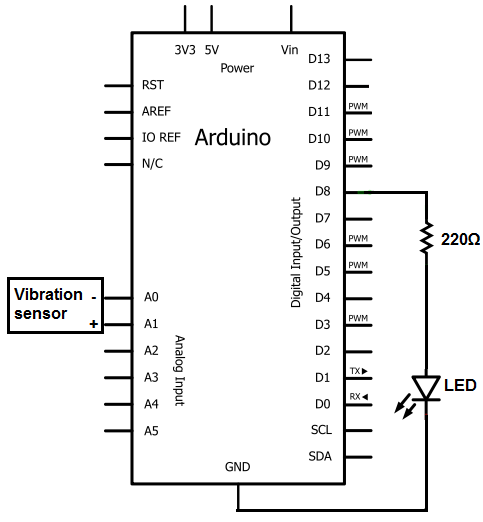
The sensors consist of a thin strip of piezoelectric material with a rivet at one end acting as a weight. When vibration occurs, the weight moves, stressing the piezo material, which generates a spike in voltage that can reach...

An NE555 timer integrated circuit (IC) configured in a specific manner can identify the absence of a pulse or an unusually long duration between two successive pulses in a pulse train. Such circuits are applicable for detecting the intermittent...
This circuit is useful in liquids level or proximity detection. It operates detecting the distance from the target by reflection of an infra-red beam. It can safely detect the level of a liquid in a tank without any contact...
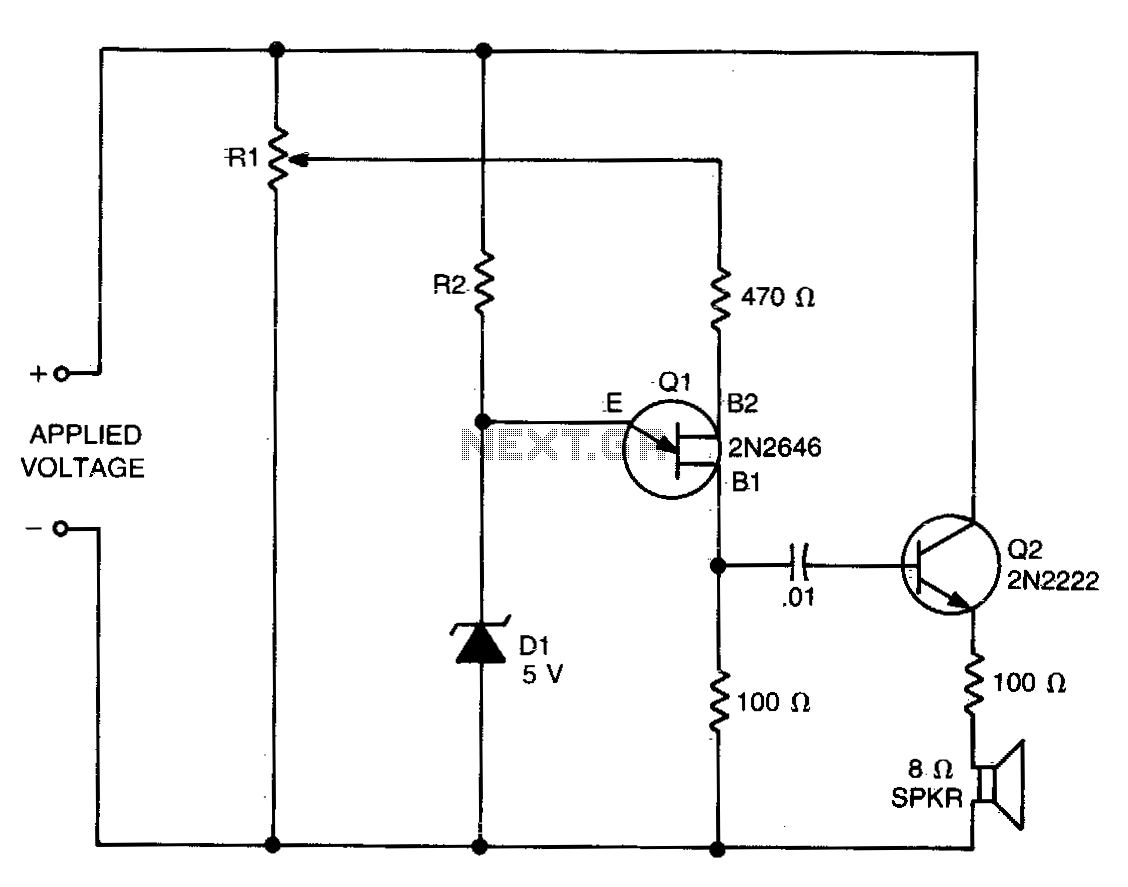
The values of R1, R2, and D1 are selected based on the voltage applied. Using a 12-volt battery, R1 is set to 10 kΩ, R2 to 5 kΩ, and D1 is a 5-volt zener diode or a string of...
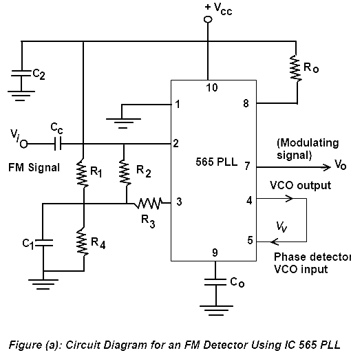
Phase Lock Loop (PLL) FM Detector with 565 PLL IC. The circuit diagram and internal structure of the PLL IC 565 are shown in the given figures. The Phase Lock Loop (PLL) FM Detector utilizing the 565 PLL IC is...