
One kind of wireless remote control circuit
The remote control transmitter design integrates a dual-tone multi-frequency (DTMF) generator with an FM transmitter to enable wireless communication. The DTMF generator, implemented using the UM91214B IC, produces specific frequency tones corresponding to the keys pressed on a telephone keypad. This IC is designed for low power operation, making it suitable for battery-powered devices. The 3V power supply is stabilized by the zener diode D1, ensuring consistent voltage levels for reliable operation of the DTMF generator.
The FM transmitter section of the circuit is constructed around a transistor (T1), which acts as the main amplification element. The tuning circuit, consisting of the inductor (L1) and the variable capacitor (VC1), is crucial for determining the transmission frequency. The inductor and capacitor form a resonant LC circuit, allowing the transmitter to operate at the desired frequency range for effective signal transmission. The variable capacitor enables fine-tuning of the frequency, accommodating for any shifts due to component tolerances or environmental factors.
Additional components may include resistors and capacitors for biasing and stabilization of the transistor, as well as any necessary coupling capacitors to interface the DTMF output with the FM transmitter input. The overall design emphasizes compactness and efficiency, making it suitable for remote control applications where space and power consumption are critical factors. The integration of the DTMF generator with the FM transmitter allows for seamless communication, enabling users to send commands wirelessly with the press of a button.The remote control transmitter is composed of the DTMF generator and the FM transmitter circuit. Here we use one piece of UM91214B phone specific IC to produce the DTMF signal, the 3V power supply voltage is supplied by the 3V zener tube D1.The transmitter circuit is composed of the transistor T1 and the external circuits, the tuning circuit L1 and VC1 is.. 🔗 External reference
Related Circuits

This document outlines the construction of a pendulum-controlled clock designed for high accuracy. Although it has a retro appeal, it represents an intriguing project. The project requires a spare quartz clock, which must be modified by isolating two pads...
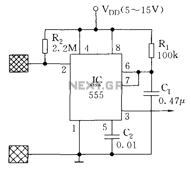
The proximity switch using the 555 timer functions as a monostable trigger circuit. The trigger pin (Pin 2) of the 555 timer is connected through a large resistor (R2) to the positive supply voltage (VDD) and is in a...
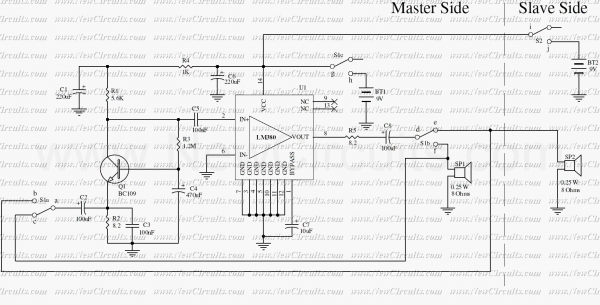
Very simple and useful circuit for communication between two persons. The Q1 is used to amplify the weak output signal of the speaker when one pushes his (her) side push-button to speak. The base-common configuration of the Q1 pre-amplifier...
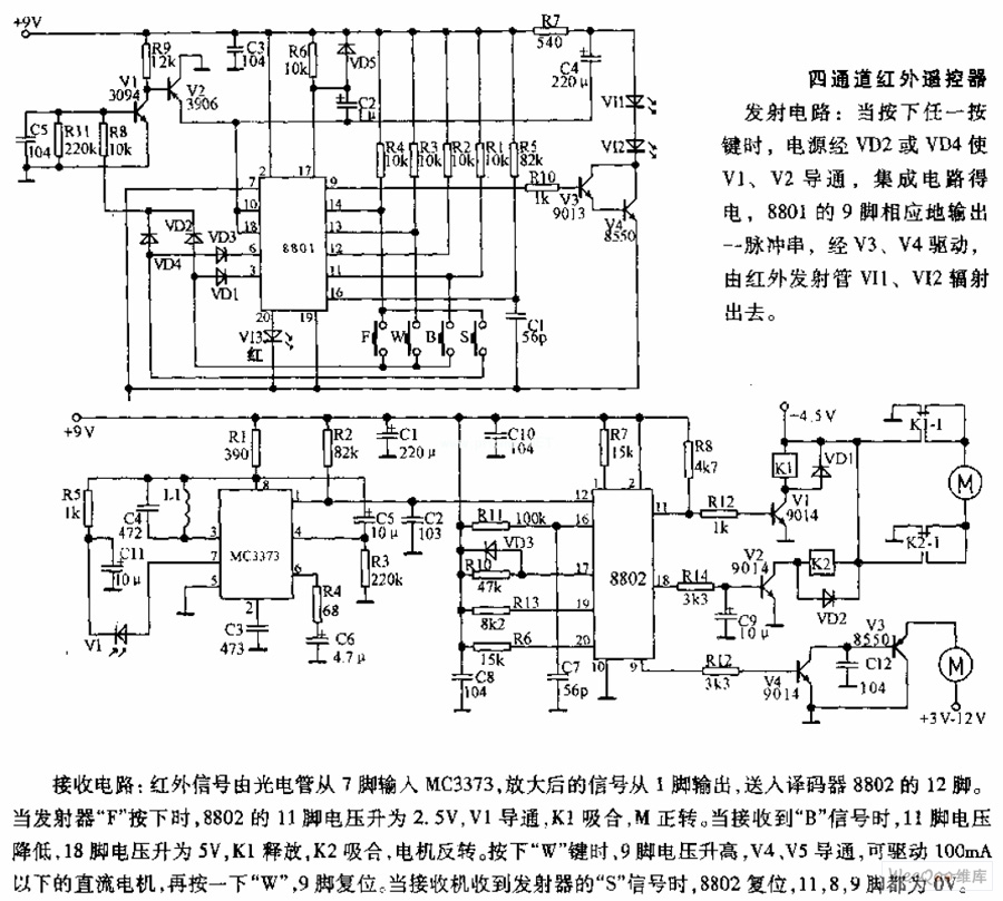
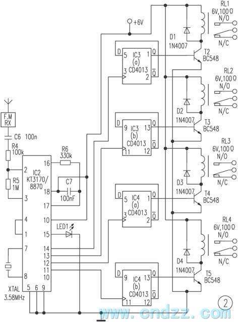
The receiving circuit involves an infrared signal being input to the MC3373 from pin 7 via a phototube. The amplified signal is output from pin 1 and sent to pin 12 of the decoder 8802. When the transmitter F...

An ultrasonic cleaner is effective for cleaning specific items. This circuit employs a microcontroller to manage timing and provide a digital display, although a basic oscillator can be utilized if preferred. RESL and RES2 are piezoelectric transducers activated by...
The SE555/NE555 timer was first introduced by the Signetics Corporation around 1971. Pin connections and functions are as follows: Pin 1 (Ground) - This pin serves as the ground or common pin, representing the most negative supply potential of...