
Car Parking Sensor Circuit Schematic Free With Explanation
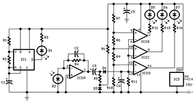
The circuit operates by utilizing infrared light to detect the proximity of objects, specifically the wall of a garage when parking. The core of the system is an oscillator circuit formed by IC1, which generates a series of pulses that drive the infrared LED (D1). The emitted infrared light travels towards the wall and is reflected back to the receiving LED (D2). The distance to the wall can be gauged by measuring the time it takes for the light to return, although in this design, the reflected light's intensity is directly correlated with the distance.
The reflected signal from D2 is then amplified by IC2A to ensure that it is strong enough for further processing. The peak detection stage, which includes D4 and C4, converts the varying signal into a stable DC voltage that represents the distance to the reflecting surface. The voltage levels are then compared against predefined thresholds set by a resistor divider network (R7-R10), which establishes the reference voltages for the voltage comparators.
As the vehicle approaches the wall, the increasing intensity of the reflected infrared light results in a corresponding increase in the DC voltage output. When this voltage surpasses the thresholds set by the comparators, the LEDs (D5, D6, D7) are activated in a sequential manner, providing a visual indication of how close the vehicle is to the wall. This visual feedback enhances the driver's awareness, helping to prevent collisions with the wall during parking maneuvers.
The design can be adapted for various applications beyond parking assistance, such as in liquid level sensing where the distance to the liquid surface can be measured, or in other proximity detection systems. Adjustments in the choice of infrared LEDs and the configuration of the circuit can optimize performance for different reflecting surfaces and environmental conditions.This circuit was designed as an aid in parking the car near the garage wall when backing up. LED D7 illuminates when bumper-wall distance is about 20 cm. , D7+D6 illuminate at about 10 cm. and D7+D6+D5 at about 6 cm. In this manner you are alerted when approaching too close to the wall. All distances mentioned before can vary, depending on infra-re d transmitting and receiving LEDs used and are mostly affected by the color of the reflecting surface. Black surfaces lower greatly the device sensitivity. Obviously, you can use this circuit in other applications like liquids level detection, proximity devices etc.
IC1 forms an oscillator driving the infra-red LED by means of 0. 8mSec. pulses at 120Hz frequency and about 300mA peak current. D1 & D2 are placed facing the car on the same line, a couple of centimeters apart, on a short breadboard strip fastened to the wall. D2 picks-up the infra-red beam generated by D1 and reflected by the surface placed in front of it. The signal is amplified by IC2A and peak detected by D4 & C4. Diode D3, with R5 & R6, compensates for the forward diode drop of D4. A DC voltage proportional to the distance of the reflecting object and D1 & D2 feeds the inverting inputs of three voltage comparators.
These comparators switch on and off the LEDs, referring to voltages at their non-inverting inputs set by the voltage divider resistor chain R7-R10. 🔗 External reference
Related Circuits
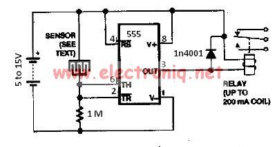
The water sensor circuit utilizes a 555 timer circuit along with common electronic components. It consists of two metal electrodes positioned closely enough that a drop of water can create a conductive bridge between them. If the water is...
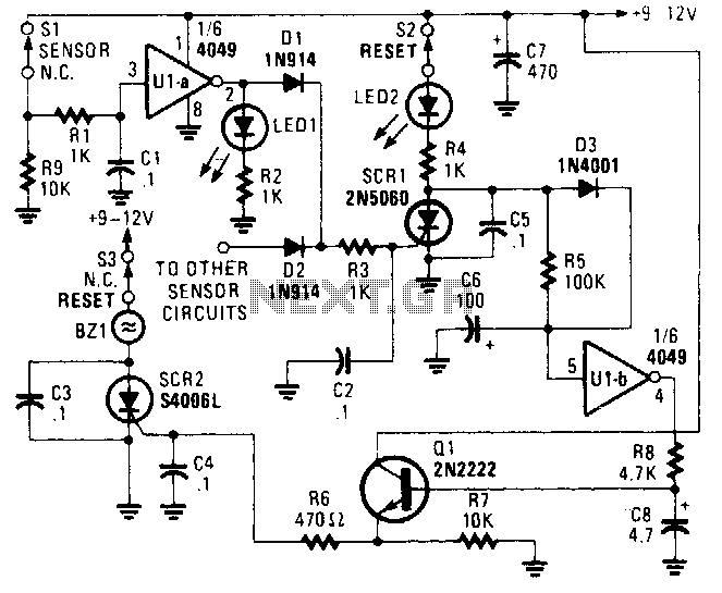
The alarm/sensor circuit is constructed using two SCRs, a transistor, a 4049 hex inverter, and several supporting components, which together create a closed-loop detection circuit featuring a delay mechanism. This delay allows entry into a protected area and deactivation...
The EUA2032 is a high-efficiency, 2.5W mono class-D audio power amplifier. A newly developed filterless PWM modulation architecture further reduces EMI and THD+N, as well as eliminates the LC output filter, thereby reducing the external component count, system cost,...
The mixer features two stereo phono inputs and two stereo line-level inputs, along with one stereo bonded channel. It also includes a microphone input and a stereo output with adjustable gain. The mixer is designed to accommodate a variety of...
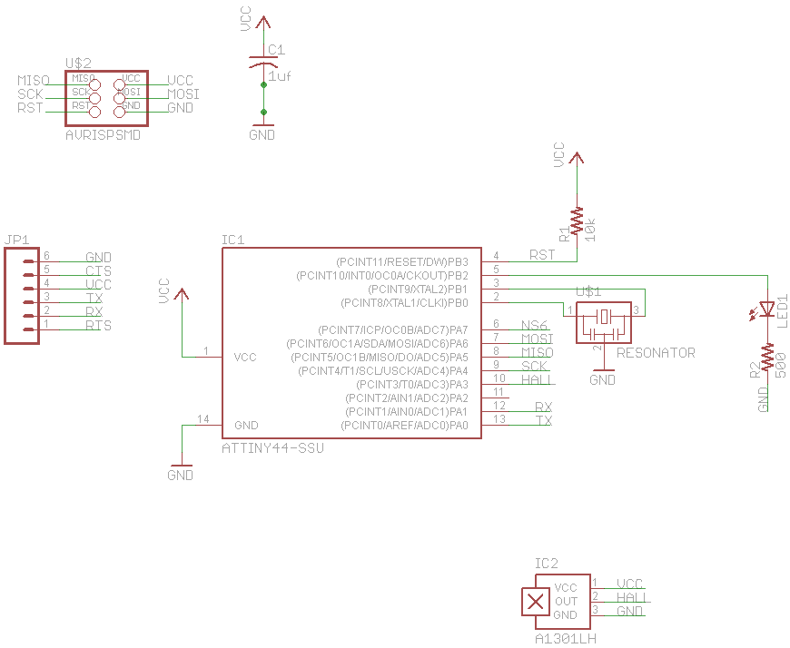
The final project involves cycling rollers that require a method to sense the rotational speed of one of the rollers. Speed sensors on bicycles typically function by detecting a magnet attached to a spoke on one of the wheels...
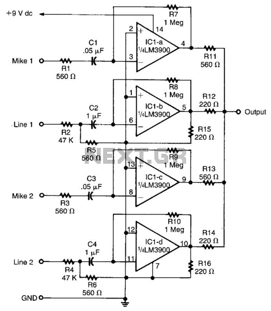
Designed around an LM3900 quad op amp, this mixer combines two line inputs and two microphone inputs, summing them at the output terminal. Resistors R7 through R10 can be adjusted to vary the gain, approximately +23 dB. The mixer circuit...