
Car Reverse Horn
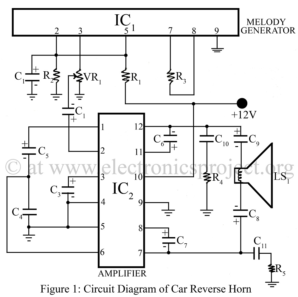
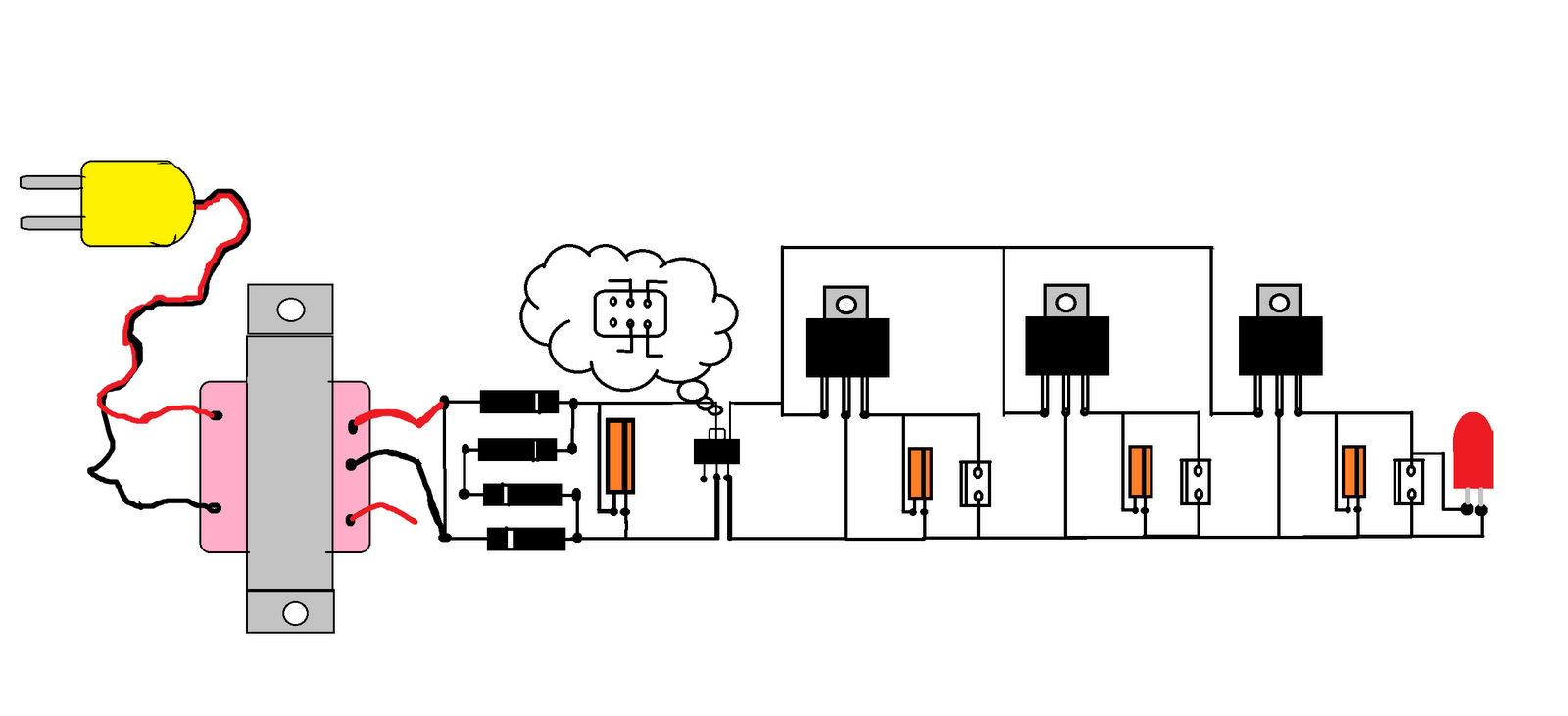
The Car Reverse Horn circuit operates by generating a melody or sound that alerts pedestrians and other vehicles of the car's movement in reverse. The CTC2877 melody generator IC is responsible for producing a specific tune or sound sequence, which is essential for making the reverse horn more noticeable and less monotonous than a standard beep. This IC can be programmed to produce various melodies, enhancing safety and awareness in busy environments.
The amplifier IC AN7148 is employed to boost the output signal from the CTC2877, ensuring that the generated sound is loud enough to be heard over ambient noise. The integration of these two ICs allows for a compact and efficient design, suitable for automotive applications.
The circuit typically includes a power supply section, which may consist of a voltage regulator to ensure stable operation of the ICs. Additionally, a speaker or piezoelectric buzzer is connected to the output of the AN7148 to produce the audible sound. The overall circuit may also include components such as resistors and capacitors to filter and stabilize the audio output, as well as a switch or sensor that activates the reverse horn when the vehicle is shifted into reverse gear.
This design not only adds an element of safety to vehicle operation but also allows for customization of the sound, catering to individual preferences or regulatory requirements. This versatility makes the Car Reverse Horn a valuable addition to modern automotive electronics.Car Reverse Horn can be used in car as reverse horn circuit diagram using melody generator IC CTC2877 and amplifier IC AN7148.various automobile project with description. 🔗 External reference
Related Circuits
When the amplifier is installed inside the suitcase, it will require a change to stop working. The LA47536 has a control pin (pin 4) that requires a small voltage of up to 2V to turn on the amplifier. Transistors...
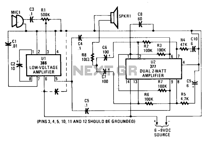
The input audio signal is connected to pin 3 of U1, an LM386 low-voltage amplifier, through capacitor C3 and resistor R1. The potentiometer R1 adjusts the drive or volume level. U1 functions as a driver stage, with a gain...
The brake lights of the automobile activate this circuit intermittently. This prevents unnecessary alarm activation when it is not required. Although this is an older circuit originally published in Popular Electronics Magazine, it remains effective today. The described circuit utilizes...
This document explains how to create a wireless car using integrated circuits (ICs) and requires additional components such as registers. It is recommended to visit an electronics shop to purchase a wireless car kit operating at 413 MHz ASK...
The SN75604, which features input control logic and requires only a single supply rail, can be utilized in light activation sensors and alarm drivers. The device's Vqq and enable inputs are connected to a voltage lead from the light...
This simple circuit drives six LEDs in a "Knightrider scanner mode." Power consumption primarily depends on the type of LEDs used, particularly when employing a 7555 (555 CMOS version). The circuit operates by sequentially illuminating the LEDs to create a...