
Car windshield wiper delay

More: The SI operates using +12 V from the vehicle's battery, which is fed into a voltage doubler that generates +18 V. This elevated voltage is essential for reliably turning on transistor Q1 through the V2 multivibrator. The configuration provides approximately +18 V to the gate of Q1, with its source voltage being less than +12 V, accounting for the V_DS drop across Q1.
Transistor Q1 remains activated for a duration determined by the interval set by the WIPES potentiometer, which is adjusted by the pause control. When the capacitor C1 discharges below V + 4, the operational amplifier U2 is triggered, turning on Q1 and initiating the wiper cycle again.
The circuit employs a multivibrator configuration that ensures smooth operation of the windshield wipers, allowing for a controlled delay between wipes. The use of a voltage doubler not only enhances the voltage available for the control circuitry but also improves the responsiveness of the wiper system. The design is focused on safety and efficiency, ensuring that wiper blades return to a non-obstructive position while maintaining optimal visibility for the driver. The integration of the potentiometer allows for user customization of the wipe interval, adapting to varying weather conditions and driver preferences.The circuit provides a windshield wiper delay, dynamic braking and windshield wipers when they reach the rest position. This prevents the blades passing, which could lead them to stop at a point where they interfere with the vision of drivers.
With the original wiper switch off, switch turns on the MLS delay circuit and disconnects the wiring SIB from automobiles. When SI is turned off, the original wiring system and controls the delay circuit is bypassed. Regarding the SI uses the + 12 V to VI of the battery is a voltage doubler which produces + 18 V. This supply higher voltage is needed to ensure reliable turn on Ql through V2 multivibrator. This arrangement provides about +18 V to the gate of Ql, whose source is less than + 12 V drop V DS Ql. Ql stays on for a time determined by the interval between wipes WIPES potentiometervThe is controlled by the pause control when Cldrops below V + 4, U2 lights, turning on Ql and repeat the cycle.
Related Circuits
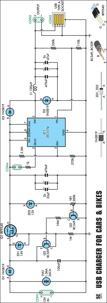
An efficient USB charger designed to operate from a 12V car battery, achieving up to 89% efficiency and capable of charging USB devices at currents up to 525mA. It does not drain the battery if left permanently connected, provided...
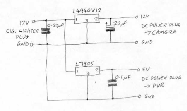
There is now no need for a separate camera and recorder; for a lower cost, an integrated dash camera that records in HD can be obtained. The Techmoan blog offers reviews on these devices. This text describes the installation...
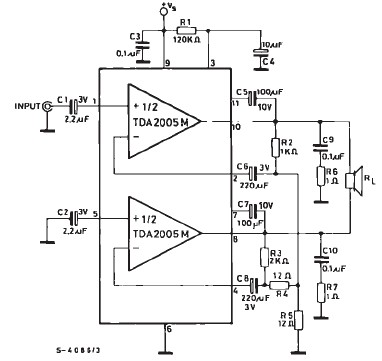
TDA2005 car audio amplifier circuit diagram electronic project using few external electronic parts The TDA2005 is a robust integrated circuit designed for audio amplification in automotive applications. This circuit diagram outlines a project for a car audio amplifier that utilizes...
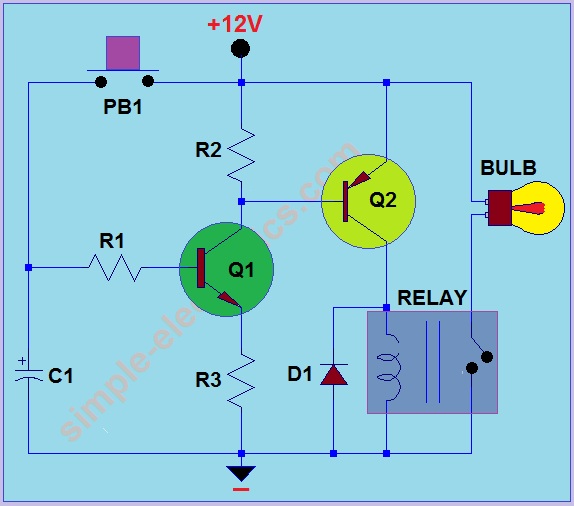
This circuit operates by activating a headlight when the push-button PB1 is pressed. The headlight remains illuminated for a predetermined duration, which can range from several seconds to minutes, before automatically turning off. When PB1 is engaged, capacitor C1...
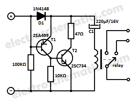
Protect your equipment with this compact 12V time delay relay circuit. The SMPS-based power supply of modern electronic devices is susceptible to voltage spikes. This 12V time delay relay circuit is designed to safeguard sensitive electronic devices by providing a...
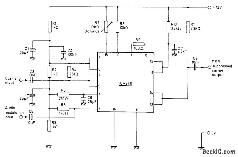
The Mullard TCA240 is a dual balanced modulator-demodulator that effectively suppresses the carrier frequency at the output, which is essential for Single Sideband (SSB) or Double Sideband (DSB) operation in transmitters. The bias resistor R7 is adjustable to achieve...