
Car Wiper Controller
The circuit operates by utilizing two NE555 timer ICs, where IC1 is configured in a monostable mode to generate a single pulse when activated by switch S1. This pulse serves as a clock signal for the CD4017 decade counter (IC2), enabling it to progress through its ten outputs sequentially with each press of S1. The configuration allows for a variable wiper speed, as the outputs of IC2 are connected to ten variable resistors (VR1 to VR10), each preset to different resistance values to achieve distinct timing intervals.
The selected output from IC2 is connected in series with resistors R4 and R5, which are part of the timing circuit for the second NE555 timer (IC3) operating in astable mode. The astable configuration of IC3 allows it to generate a continuous square wave signal, with the frequency of oscillation determined by the selected preset resistor value. This frequency corresponds to the desired wiper sweep speed, varying from once every second to once every ten seconds depending on the position of the selected preset.
The output from IC3 drives a PNP transistor (TIP32), which acts as a switching device to control the larger power transistor (2N3055). The power transistor is responsible for supplying the necessary current to the wiper motor, thereby controlling its operation based on the frequency provided by the astable multivibrator. The entire circuit is powered by the vehicle's battery, ensuring that the wiper system operates efficiently within the automotive environment. The design allows for a practical solution to manage wiper operation, enhancing user convenience and improving visibility during varying weather conditions.A continuously working wiper in a car may prove to be a nuisance, especially when it is not raining heavily. By using the circuit described here one can vary sweeping rate of the wiper from once a second to once in ten seconds.
The circuit comprises two timer NE555 ICs, one CD4017 decade counter, one TIP32 driver transistor, a 2N3055 power transistor (or TIP3055) and a few other discrete components. Timer IC1 is configured as a mono- stable multivibrator which produces a pulse when one presses switch S1 momentarily.
This pulse acts as a clock pulse for the decade counter (IC2) which advances by one count on each successive clock pulse or the push of switch S1. Ten presets (VR1 through VR10), set for different values by trial and error, are used at the ten outputs of IC2.
But since only one output of IC2 is high at a time, only one preset (at selected output) effectively comes in series with timing resistors R4 and R5 connected in the circuit of timer IC3 which functions in astable mode. As presets VR1 through VR10 are set for different values, different time periods (or frequencies) for astable multivibrator IC3 can be selected.
The output of IC3 is applied to pnp driver transistor T1 (TIP32) for driving the final power transistor T2 (2N3055) which in turn drives the wiper motor at the selected sweep speed. The power supply for the wiper motor as well as the circuit is tapped from the vehicles battery itself.
The duration of monostable multivibrator IC1 is set for a nearly one second period. 🔗 External reference
Related Circuits
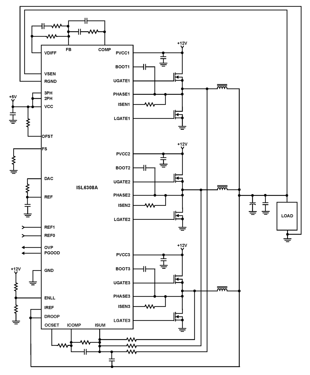
The ISL6308A is a three-phase PWM control integrated circuit (IC) equipped with built-in MOSFET drivers. It delivers precise voltage regulation suitable for various applications, including high current low voltage point-of-load converters, embedded systems, and other general low voltage medium...
When we step on the car's brake, then together with the classic rear STOP, the third STOP which is situated in the middle of the back half of the car also switches ON. This is the classic function, found...
Several weeks ago, a situation arose where there were no telephones left to restore. All payphone projects had been completed and were now collecting dust on shelves. A desire emerged to create a unique, creative, and useful project for...
This rotary speed regulator circuit schematic enables control over the rotational speed of a borer or drilling machine. This project is based on the principle that... The rotary speed regulator circuit is designed to modulate the speed of electric motors...

A stepper motor provides a simple, low-cost, and precise method for position control. It can be driven by a circuit that is mounted near the motor and controlled by a microcontroller. Stepper motors are widely utilized in applications requiring precise...
This 555 timer based PWM controller features almost 0..100% pulse width regulation using R1, while keeping the oscillator frequency relatively stable. The frequency is dependent on values of R1 and C1, values shown will give a frequency range from...