
cars brake lights monitor circuit

The circuit operates by monitoring the voltage levels across the brake light supply lines. When the brake pedal is pressed, the voltage drop across the lamps is detected by the Schmitt trigger formed by transistors T1 and T2. This configuration provides hysteresis, ensuring stable operation by preventing false triggering due to noise or minor fluctuations in voltage.
The LED (D1) serves as a visual indicator of the brake light status. When both brake lights are functional, the voltage drop is sufficient to keep the LED off. If one light fails, the remaining light will draw more current, causing the voltage drop to exceed the threshold, which activates D1 momentarily. If both lights are inoperative, the LED remains off, indicating a complete failure.
Adjusting the sensitivity of the circuit via potentiometer P1 allows for calibration based on the specific characteristics of the brake lights used. This feature is crucial for ensuring consistent performance across different vehicle models and lamp types.
In the alternative configuration with the BC547B transistor, the circuit's behavior changes, providing a simpler indication of a fault without differentiating between one or both lights being out. This modification may be preferable in applications where simplicity is desired over detailed diagnostics.
Overall, this circuit enhances vehicle safety by providing a straightforward method to monitor brake light functionality, allowing for timely maintenance and reducing the risk of accidents due to non-operational brake lights.The circuit described below monitors your car`s brake lights, and indicates by a light emiting diode 12V whether they both function correctly. In that sense, it can save you money by preventing your being fined for driving with defective brake lights, and it also leads to increasing road safety.
The monitor depends inevitably on the voltage drop a cross the supply lines to the two lamps. For the circuit to work correctly, that drop needs to be greater than 0. 6 V. If this is not so, the drop must be in- creased by adding a 5 V diode in series with each lamp. Transistor Ti and T2 in figure 1 form a Schmitt trigger, which reacts to the voltage drop across the supply lines to the two brake lights. This reaction manifests itself in Di lighting via T3. If one of the brake lights is faulty, the switch-on cur- rent drawn by the other lamp will cause Di to light briefly when the brake pedal is pressed.
If both brake lights are defective, Di will not light at all. All three possible states of the brake lights are thus indicated. sitivity of the circuit, can be adjusted within narrow limits with Pi. The preset is best adjusted with one lamp out of action in a manner which makes Di light briefly as described above. If you find it disturbing that Di lights every time you brake, the operation can be reversed by replacing the BC557B in the T3 position by a BC547B (n-p-n).
The collector of T3 is then connected to the positive supply line, and the emitter to R6. On the printed circuit board this means that the flat edge of T3 must be turned the other way. A second base connection has also been provided on the PCB. Note, however, that this configuration no longer makes it possible to ascertain whether one or both brake lights are faulty, i. e. , when the LED lights, one or both lamps need replacing. 🔗 External reference
Related Circuits

The circuit is designed to switch off a specific lamp or a group of lamps based on varying ambient light levels. Once constructed, it will turn off a lamp at dawn and turn it on at dusk. The power...
A DC-to-DC step-up converter is typically implemented using a transformer, which converts DC voltage to AC voltage, steps it up with the transformer, and then rectifies and filters the output to achieve a higher DC voltage. However, a voltage...

The CS5501 16-bit delta-sigma analog-to-digital converter continuously converts signals, outputting conversion words to its output register every 1024 cycles of its master clock, as it lacks a start convert command. By integrating a standard dual J-K flip-flop into the...
This series-feedback configuration of compounds provides a high input impedance and stable, wide-band gain video amplifier suitable for general-purpose applications. It features low capacitance and high impedance. The described video amplifier circuit utilizes a series-feedback topology to achieve high input...
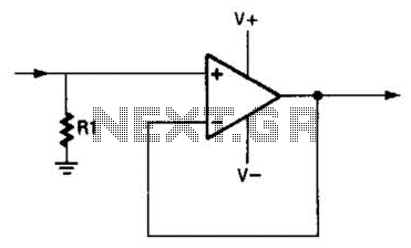
An operational amplifier (op amp) can function as a unity gain amplifier by connecting its output to its inverting input as illustrated. The load resistance (Rl) should be sufficiently low to prevent the op amp's bias current from introducing...
This circuit generates a two-tone effect similar to the cuckoo song. It can be utilized for doorbells or other applications due to its integrated audio amplifier and loudspeaker. As a sound effect generator, it can connect to external amplifiers,...