
Catching the Falling Drop
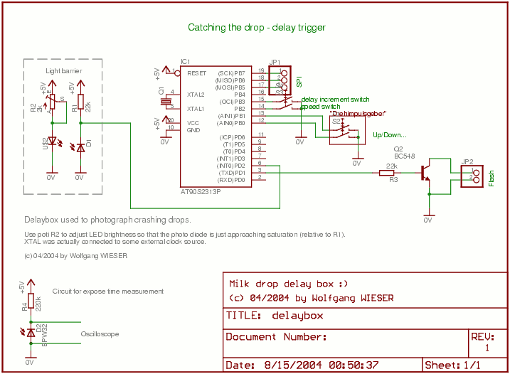
To achieve the desired functionality, the circuit design incorporates several key components. The Atmel `2313 microcontroller serves as the core processing unit, managing the timing and triggering of the flash. The microcontroller is programmed to count clock cycles generated by the 1 MHz oscillator, allowing for precise timing control. The SPI interface connects the microcontroller to the Latch16Bit board, facilitating communication and programming of the controller.
The light barrier, consisting of an infrared LED and a phototransistor, detects the presence of the falling drop. When the drop interrupts the light beam, the microcontroller receives a signal indicating the drop's entry. The software running on the microcontroller processes this input, calculating the appropriate delay before firing the flash. This delay is adjustable via the switch, allowing for fine-tuning based on experimental observations.
The photo flash is connected to a transistor that acts as a switch, controlled by the microcontroller's output. Upon reaching the specified delay, the microcontroller sends a signal to the transistor, triggering the flash to illuminate the scene at the precise moment the drop is captured.
The entire system is powered by a stable voltage source, ensuring consistent operation of the microcontroller and the light barrier. Proper grounding and decoupling capacitors are included to minimize noise and ensure reliable performance.
Overall, this setup provides an effective solution for capturing high-speed events with sub-millisecond accuracy using accessible components, demonstrating the potential of combining simple electronics with creative problem-solving in experimental photography.The goal is to take photos of some fairly quick process (well, at least too quick for the human eye) at exactly specified times with sub-millisecond accuracy. Of couse, with expensive special equipment at hand (such as a high speed camera), this is a trivial joke, but I wanted to do it in my room with the stuff and "toys" I have laying around as w
ell as a normal digital camera (Minolta) and an ordinary photo flash. The camera has a much too long delay from pressing the button until the exposure actually begins so one has no chance to catch the drop this way. Furthermore, the minimum expose time is 1ms but it would be better to further reduce it in order to get sharper images.
So, the basic idea is to make the room dark, open the camera`s shutter, let the drop fall down, fire the photo flash at the correct time and close the shutter again. To provide me with drops in roughly constant intervals, I used a standard pipett with some toilet paper inside to drastically limit the liquid flux.
The method worked surprisingly reliable. Checking out my electronics stuff, I found a transmission light barrier extracted from a very old floppy drive which was just wide enough to get the drop though (after having adjusted the drop source position). On the left you can see an image of the light barrier together with a milk drop which just went through it.
Especially note that the drop is completely spherical and has no special "drop-like" shape. Still needed, however, was the delay trigger to fire the flash light some specified time after the drop crosses the light barrier. For the height I was using, the base delay until the drop crashes was about 1/4s to 1/2s (250-500ms).
To see the different stages of the crash, some precisely defined amount of time in the order of single milliseconds must be added to this time. It took me half a day to get a working sub-millisecond precision delay trigger for the drops: First, I played around with various RC-based solutions but they all could not attain the precision (if they worked reliable at all) and had the principal inconvenience that I would need to calculate the time from the rotation angle of a potentiometer.
A further problem was due to the fact that the light barrier could fire two peaks for each drop of transparent liquid: one upon entering and one upon leaving since the drop is about as transparent as air while being just in the middle of the light barrier. I finally settled down with a really easy microcontroller-based circuit: A 1MHz clock source was driving an Atmel `2313 AVR RISC connected via SPI and the Latch16Bit board with my computer.
The latter was only needed to hack together, compile and download the firmware of the controller which took about an hour. A switch was attached to the Microcontroller to increase/decrease the delay time from the first falling edge of the light barrier until firing the flash.
Sub-millisecond precision was achieved easily by having the AVR RISC counting its own clock (i. e. executing a defined number of instructions) so that overall timer accuracy was a couple of microseconds. 🔗 External reference
Related Circuits
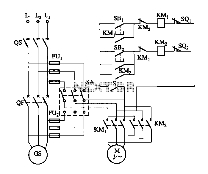
FIG M is a variable speed motor control for the opening and closing of a wicket gate. It features an electric governor. The system is activated by a power switch (SA) located on the front grid, and a toggle...
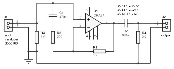
Hydrophone preamplifier circuit. It is simple and utilizes only conventional components. The transducer used is of the piezo type and has a relatively high output impedance, necessitating a preamplifier with a high input impedance. The hydrophone preamplifier circuit is designed...
This may appear to be a highly detailed post; however, it is being written to assist others who are experiencing a similar frustrating search for 12V timers that possess functionalities comparable to those found in mains timers. The intention...
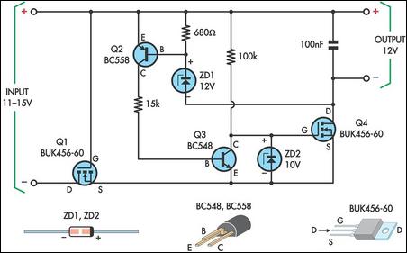
This circuit is designed to power a laptop computer using a solar power setup. The computer requires 12V at 3.3A. The circuit employs a linear regulator with a MOSFET (Q4) as the series pass device. A 100kΩ resistor provides...
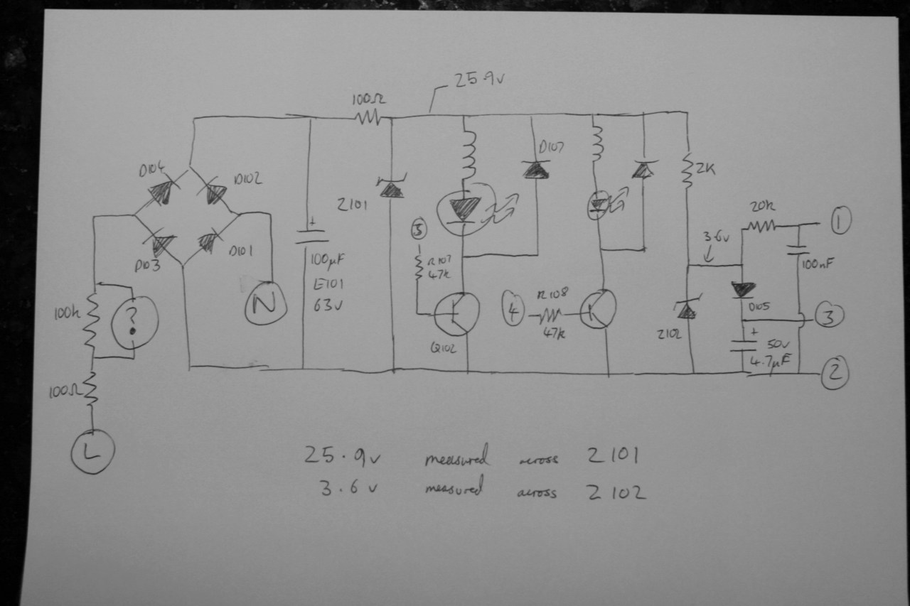
This circuit is a Low-Light Level Drop Detector. It utilizes a self-biasing configuration to detect small changes in light levels. The Low-Light Level Drop Detector circuit is designed to sense minute variations in ambient light conditions, making it suitable for...
Water drops have always captivated those interested in time-lapse and macro photography, serving as a common entry point into this fascinating field. However, further research reveals that photographing these tiny splashes involves more complexity than initially apparent, as the...
Warning: include(partials/cookie-banner.php): Failed to open stream: Permission denied in /var/www/html/nextgr/view-circuit.php on line 713
Warning: include(): Failed opening 'partials/cookie-banner.php' for inclusion (include_path='.:/usr/share/php') in /var/www/html/nextgr/view-circuit.php on line 713