
ceiling fan regulator motor speed

The ceiling fan regulator circuit operates on the principle of phase control, allowing for the adjustment of the voltage supplied to the ceiling fan motor, thereby modulating its speed. The Z0607 TRIAC acts as a switch that can turn on and off the current flow to the motor, effectively controlling its speed based on the phase angle of the AC waveform.
The variable resistor (R1) allows the user to fine-tune the amount of current reaching the motor, providing a range of speed settings from low to high. The capacitor (C1) is essential for stabilizing the circuit and ensuring smooth operation. It helps in filtering out voltage spikes that could potentially damage the TRIAC or the motor.
In summary, this circuit is an efficient and simple solution for controlling the speed of ceiling fans, utilizing minimal components while providing reliable performance. The use of the TRIAC enables effective control of AC power, making it suitable for various applications where speed regulation of AC motors is required.This is a simple ceiling fan regulator circuit diagram. It is used to control the speed of a ceiling fan. In the other words it is an AC motor speed controller circuit, as because its control the speed of a AC motor(Ceiling Fan). This ceiling fan regulator circuit built with few numbers of parts. The circuit mainly based on Z0607 TRIAC. This is a low power AC semiconductor device. Generally which is used to controlling speed of low power ac motor speed. In this ceiling fan regulator circuit, R1=500K is a variable resistor that is used to adjust the fan speed. Capacitor C1 2A104J is a Polyester film capacitor. Parts List Ceiling Fan Motor Speed Controller circuit: 🔗 External reference
Related Circuits
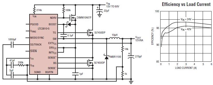
The LTC3810-5 synchronous step-down switching regulator controller allows for the design of a straightforward 12-volt switching power supply electronic project with minimal external components. This controller can directly reduce voltages from up to 60V, making it suitable for telecommunications...
The design of solar panel systems with a lead-acid buffer battery typically allows for battery charging even during low sunlight conditions. However, this necessitates the use of a regulator to prevent overcharging during periods of abundant sunshine. Common solutions...
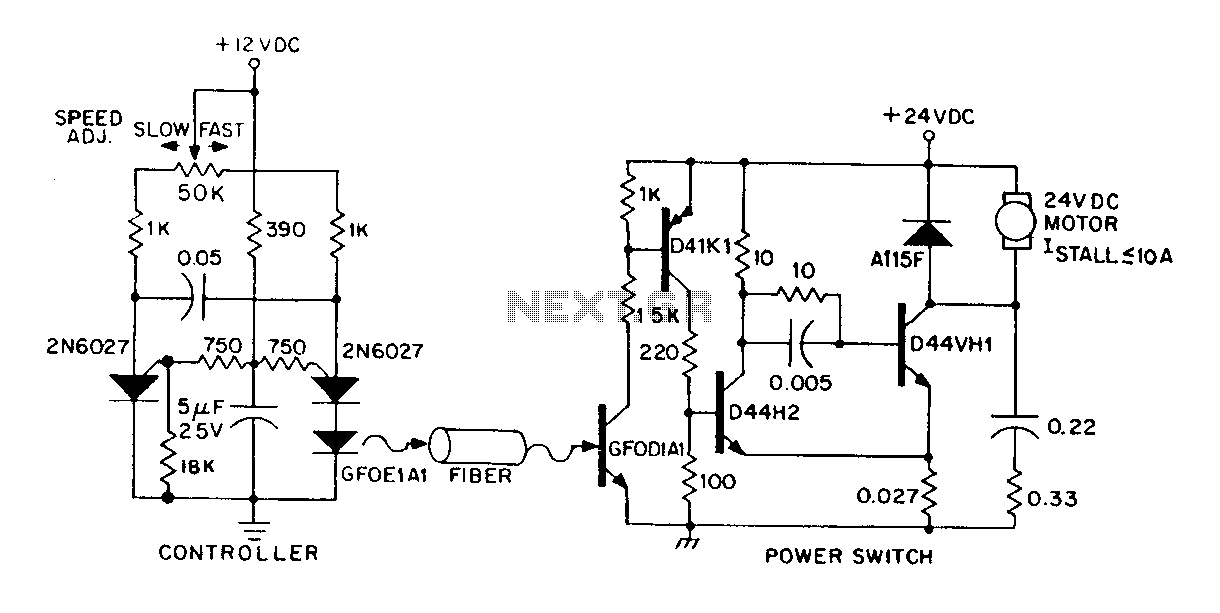
A DC power supply can be controlled through an optical fiber. The circuit includes a small DC motor (1/12 hp) that offers an isolated speed control channel. The control logic operates as an independent module, consuming 300 mW of...
The Scorpion jammers operate by sending back a constantly varying Doppler shift instead of a fixed Doppler shift corresponding to a specific speed. Some units may not display readings, while others show continuously changing data. Other devices have transmitted...
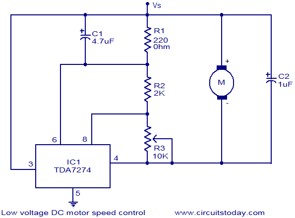
The circuit diagram illustrates a low voltage/low power DC motor speed controller utilizing the TDA 7274 integrated circuit from ST Microelectronics. The TDA 7274 is designed for low voltage and low power applications, featuring an internal voltage reference, a...
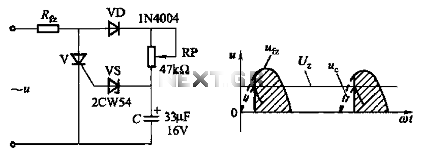
Circuit characteristics: A simple phase shift range of 180 degrees; exhibits good linearity and control accuracy compared to the first two options, making it suitable for low voltage applications, particularly in less demanding electroplating and electrolysis power supplies. The described...