
lead acid battery regulator for

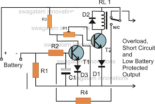
The described solar panel system utilizes a sophisticated energy management approach to maximize efficiency and ensure safe operation. The primary components include the solar panels, the lead-acid buffer battery, the shunt resistor, and the control circuitry featuring transistors and comparators. The energy diversion mechanism is critical for optimizing the use of solar energy, allowing for real-time adjustments based on the battery's charge state. By integrating a secondary battery charging option, the system can further enhance energy utilization, making it suitable for various applications such as refrigeration, water pumping, and ventilation. The incorporation of hysteresis in the comparator design ensures stable operation, reducing the risk of oscillation and improving reliability. The gradual switching characteristics provided by the capacitors not only enhance performance but also contribute to the longevity of the components by minimizing thermal stress. Overall, this circuit design exemplifies a practical solution for efficient solar energy management, addressing common challenges associated with battery charging in solar applications.The design of solar panel systems with a (lead-acid) buffer battery is normally such that the battery is charged even when there is not much sunshine. This means, however, that when there is plenty of sunshine, a regulator is needed to prevent the battery from being overcharged.
Such controls usually arrange for the superfluous energy to be dissip ated in a shunt resistance or simply for the solar panels to be short-circuited. It is, of course, an unsatisfactory situation when the energy derived from a very expensive system can, after all, not be used to the full. The circuit presented diverts the energy from the solar panel when the battery is fully charged to another user, for instance, a 12V ice box with Peltier elements, a pump for drawing water from a rain butt, or a 12V ventilator.
It is, of course, also possible to arrange for a second battery to be charged by the super-fluous energy. In this case, however, care must be taken to ensure that when the second battery is also fully charged, there is also a control to divert the superfluous energy.
The shunt resistance needed to dissipate the superfluous energy must be capable of absorbing the total power of the panel, that is, in case of a 100W panel, its rating must be also 100 W. This means a current of some 6 8 A when the operating voltage is 12 V. When the voltage drops below the maximum charging voltage of 14. 4V growing to reduced sunshine, the shunt resistance is disconnected by an n-channel power field effect transistor (FET), T1.
The disconnect point is not affected by large temperature fluctuations because of a reference voltage provided by IC1. The necessary comparator is IC2, which owing to R9 has a small hysteresis voltage of 0. 5V. Capacitor C5 ensures a relatively slow switching process, although the FET is already reacting slowly owing to C4.
The gradual switching prevents spurious radiation caused by steep edges of the switched voltage and also limits the starting current of a motor (of a possible ventilator). Finally, it prevents switching losses in the FET that might reach 25W, which would m a ke a heat sink unavoidable.
Setting up of the circuit is fairly simple. Start by turning P1 so that its wiper is connected to R5. When the battery reaches the voltage at which it will be switched off, that is, 13. 8 14. 4V, adjust P1 slowly until the output of comparator I C2 changes from low to high, which causes the load across T1 to be switched in. Potentiometer P1 is best a 10-turn model. When the control is switched on for the first time, it takes about 2 seconds for the electrolytic capacitors to be charged.
During this time, the output of the comparator is high, so that the load across T1 is briefly switched in. In case T1 has to switch in low-resistance loads, the BUZ11 may be replaced by an IRF44, which can handle twice as much power (150 W) and has an on-resistance of only 24 mR.
Because of the very high currents if the battery were short-circuited, it is advisable to insert a suitable fuse in the line to the regulator. The circuit draws a current of only 2 mA in the quiescent state and not more than 10mA when T1 is on.
🔗 External reference
Related Circuits

Low power 5V switching regulator power supply. Visit the corresponding page for an explanation of the related circuit diagram. The low power 5V switching regulator is designed to efficiently convert a higher input voltage to a stable 5V output while...
This is a small electronic switch that connects a battery to the equipment for a certain amount of time when a push-button is momentarily pressed. The ambient light level has also been considered; when it is dark, the display...
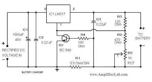
The circuit diagram of a lead-acid battery charger is presented here. The main component of this circuit is the IC LM317. The lead-acid battery charger circuit utilizing the LM317 voltage regulator is designed to efficiently charge lead-acid batteries while providing...
The battery voltage must pass through resistor R1 before reaching the output load. As a result, the current flowing through R1 is proportionately transformed into a voltage across it. When the battery voltage drops below a certain threshold, the...
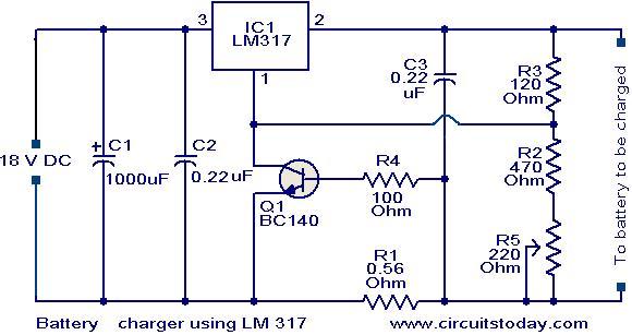
This is a simple yet effective battery charger circuit utilizing the LM317 integrated circuit (IC). The circuit is designed for charging 12V lead-acid batteries and can be easily assembled on a general-purpose printed circuit board (PCB). The core component...
A simple 12V battery charger circuit can be designed using a TIP3055 power transistor to limit the current to the battery. The circuit turns off when the battery voltage reaches approximately 14V or if the current exceeds 2A. This...