
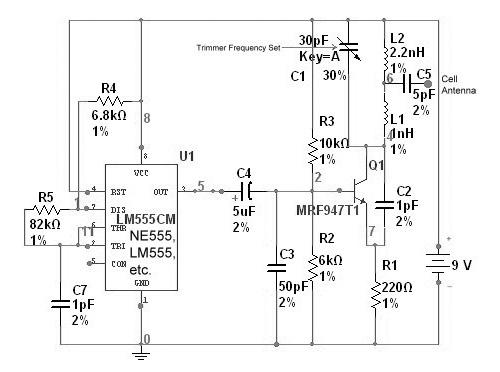
Cellular Phone Calling Detector Circuit
The circuit operates based on the principle of electromagnetic induction, where the sensor coil L1 detects the electromagnetic field produced by the cellular phone when it receives a call. The coil is designed to be sensitive enough to pick up the field without requiring direct contact with the phone.
The main components of the circuit include the sensor coil L1, a rectifier circuit to convert the alternating current (AC) induced in the coil to direct current (DC), and a microcontroller or a simple transistor-based circuit to drive the LED. The LED serves as a visual indicator of an incoming call, flashing in response to the detected signal.
To enhance the circuit's performance, the sensor coil can be tuned to a specific frequency range that corresponds to the typical operating frequencies of cellular phones. This may involve adjusting the number of turns in the coil or incorporating capacitive elements to create a resonant circuit.
In terms of power supply, the circuit can be powered by a small battery or a low-voltage power source, ensuring that it remains portable and easy to use. The entire assembly can be housed in a small enclosure that allows for easy placement near the cellular phone without obstructing its normal operation.
Overall, this circuit provides a practical solution for individuals who may need to be alerted to incoming calls discreetly, without relying on the phone's built-in ringer.This circuit was designed to detect when a call is incoming in a cellular phone (even when the calling tone of the device is switched-off) by means of a flashing LED. The device must be placed a few centimeters from the cellular phone, so its sensor coil L1 can detect the field emitted by the phone receiver during an incoming call..
🔗 External reference
Related Circuits

A useful marker oscillator can be constructed using an NE555 timer to generate pulses at an audio frequency. This design facilitates the detection of the signal even amidst interference. The crystal frequency can range from 1 to 30 MHz. The...
A "Cell Jammer" is simply another term for a "Dirty Transmitter," which transmits within the cellular phone frequency bands. In reality, the more interference it generates, the more effective it is. A cell jammer operates by emitting signals that interfere...
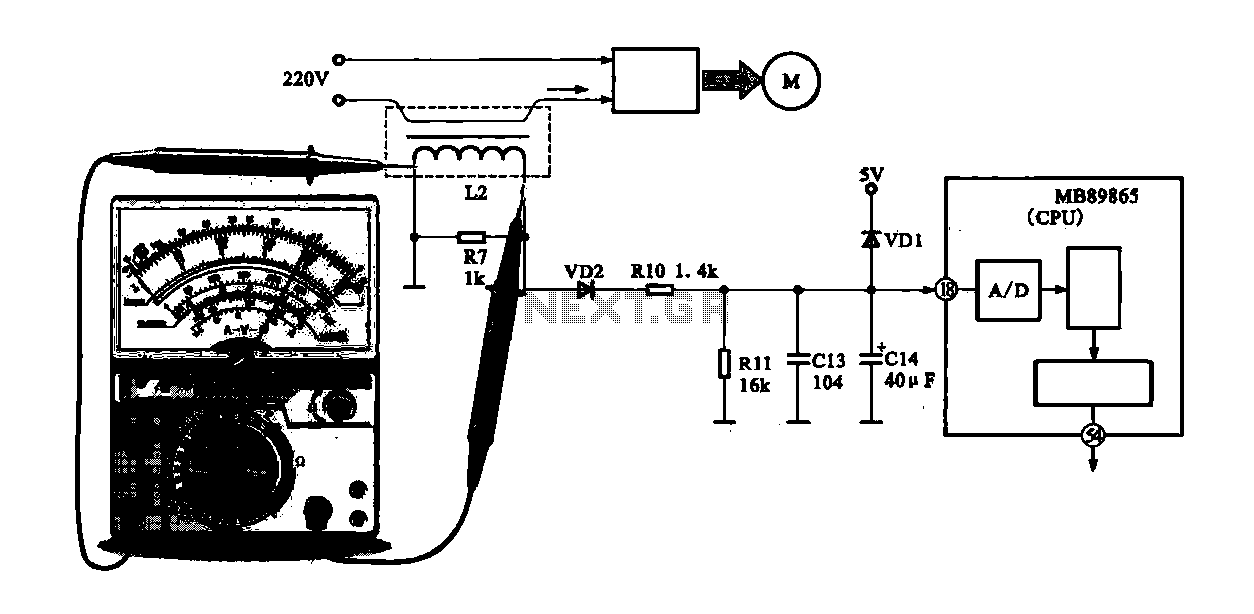
A current-voltage conversion circuit is commonly utilized in current detection applications. An example is the current detection circuit for a ring inverter air conditioner, which primarily serves to monitor the supply current of the compressor motor. Excessive current can...
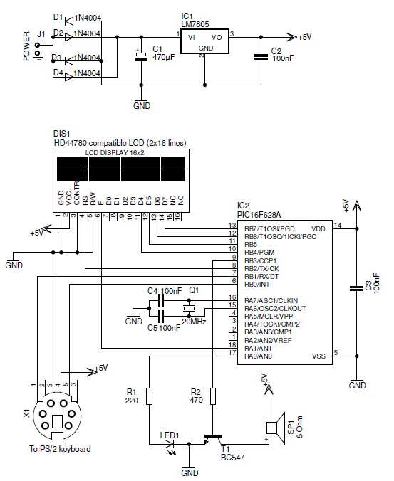
This PIC-based hardware circuit accepts texts from a PS/2 keyboard and converts it into a Morse code audio signal. The described circuit utilizes a PIC microcontroller to interface with a PS/2 keyboard, allowing for the input of alphanumeric characters. The...
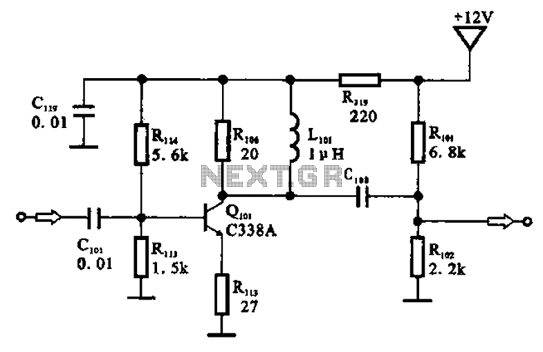
The amplifier circuit is designed as a pre-amplifier configuration. It utilizes transistor Q101 and other components such as inductor L101 and biasing elements. The transistor operates as a common emitter intermediate frequency (IF) amplifier. The IF signal is coupled...
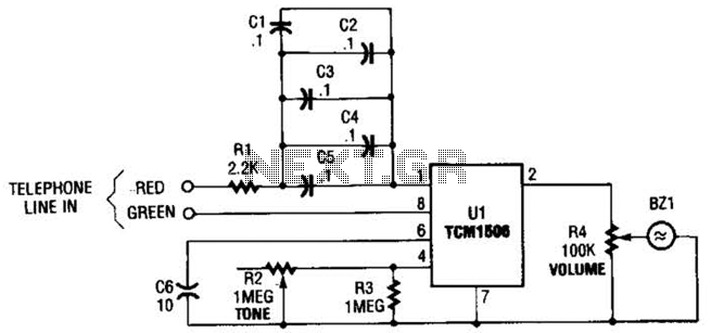
The circuit utilizes the TCM1506 ring detector/driver integrated circuit, which is a monolithic IC designed to replace mechanical bells in telephones. It is powered and activated by the telephone line's ringing signal, which ranges from 40 to 150 V...