
Cellular Phone Calling Detector Circuit Schematic

This circuit utilizes a simple yet effective approach to alert users of incoming calls through visual indication. The primary components include a light-emitting diode (LED), a transistor, and a resistor, along with a power source, which in this case is a single 1.5V battery.
The operation begins when the cellular phone receives an incoming call. A small signal from the phone's circuitry is used to trigger the transistor, which acts as a switch. When the transistor is activated, it allows current to flow from the power source through the LED. The LED then lights up, providing a visual alert to the user.
The resistor is essential for limiting the current flowing through the LED, ensuring that it operates within safe parameters to prevent damage. The value of the resistor can be calculated based on the LED's forward voltage and the desired current, typically around 20 mA for standard LEDs.
In terms of layout, the circuit should be designed to minimize the distance between the components to reduce potential signal loss. Proper grounding and power supply decoupling are also critical to ensure stable operation. Additionally, the circuit can be housed in a compact enclosure to make it portable and easy to integrate with various mobile devices.
This simple circuit design provides an effective solution for users who may miss incoming calls, enhancing the usability of cellular phones.Flashes a LED when detecting an incoming call, Powered by one 1.5V cell This circuit was designed to detect when a call is incoming in a cellular phone (e.. 🔗 External reference
Related Circuits

An AC mains operated single LED flasher circuit is constructed using the widely utilized CMOS timer chip TLC555. The entire circuit is powered directly from the 230VAC grid supply via a capacitive potential divider and associated components. This compact...

The BFP640 transistor is utilized for 1575 MHz Global Positioning Satellite (GPS) applications, specifically as a Low Noise Amplifier (LNA). The design objectives include a minimum gain of 16 dB, a noise figure of less than 0.6 dB, an...

The circuit consists of an infrared transmitter-receiver pair that uses infrared beam transmission to switch the toy car on or off. It can be modified to allow the toy car to turn left or right. To operate the toy...
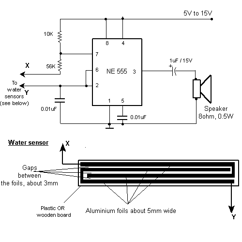
This circuit gives out an alarm when its sensor is wetted by water. A 555 astable multivibrator is used here which gives a tone of about 1kHz upon detecting water. The sensor when wetted by water completes the circuit...

The circuit SJT is a 1024 kHz warming crystal oscillator. The circuit is illustrated in the accompanying chart. Due to the low output signal level, a transistor (VT1) is employed as a buffer amplifier. The base bias resistor (R2)...

Flyback LED drivers are versatile as they can be utilized in applications with input voltages either above or below the necessary output voltages. They feature a straightforward circuit configuration that maintains a constant LED current without the need for...