
remote control receiver circuit

The infrared transmitter-receiver circuit operates by emitting a modulated infrared signal from the transmitter, which is detected by the receiver. When the receiver module TSOP1738 detects the modulated signal, it sends a corresponding output signal that can be used to control the toy car's operation. The modulation frequency typically ranges from 38 kHz, which is optimal for reducing interference from ambient infrared sources.
To modify the circuit for directional control, additional circuitry can be integrated to interpret different signals from the remote control. For instance, varying the pulse width or frequency of the infrared signals can be programmed to correspond with different movements, such as turning left or right.
The infrared remote control tester circuit serves as a diagnostic tool to ensure that the remote control unit is functioning properly. By using the TSOP1738 module, the circuit can produce an audible tone when a signal from the remote is detected, confirming that the remote is operational.
The wireless car alarm system utilizes FM radio waves for communication between the transmitter and receiver modules. This design is particularly advantageous as it allows for a greater range compared to infrared systems. The system can be powered by a 6-12V DC source, making it suitable for most vehicles. The inclusion of a voltage stabilizer ensures that fluctuations in the power supply do not affect the performance of the alarm system.
For the mini AM radio receiver circuit, the use of general-purpose transistors such as the BC549 allows for easy sourcing and replacement. The regenerative receiver design enhances sensitivity and selectivity, enabling the reception of weak AM signals. This type of circuit is beneficial for hobbyists interested in radio communications, as it provides a practical introduction to radio frequency technology.
The FM amplifier circuit, utilizing the MFE201 transistor, exemplifies a minimalist approach to audio amplification. By configuring the transistor in a common-emitter arrangement, the circuit can effectively amplify weak FM signals, providing clear audio output. The simplicity of the design allows for easy assembly and troubleshooting, making it an excellent project for electronic enthusiasts.
In summary, the described circuits offer a variety of applications ranging from remote control operations to audio reception and amplification, showcasing fundamental principles of electronics and radio frequency communication.The circuit, consisting of an infrared transmitter-receiver pair, utilizes IR beam transmission to switch the toy car on` or off`, yeah. it will be only switching on and switching off, you may modify this circuit to make the toy car to turn left or right.
To operate the toy car, you have to hold the. Here is the remote control tester circuit. Thi s circuit is really a simple and easy tester for verifying the basic operations of an infrared remote control unit. It is low-cost and very easy to construct. The tester is designed around infrared receiver module TSOP1738. Operation of the remote control is identified by a tone from. This circuit is a wireless car alarm system that is built using two circuit modules, namely modules of transmitter and receiver modules.
This circuit works on FM radio waves. Car alarms can be used on vehicles that have a 6-12VDC power supply. You can use the voltage stabilizer if your car power supply is too. This is the circuit diagram of mini AM Radio receiver. All general purpose transistors should work in this circuit, you can use BC549 transistors for this circuit. The circuit use a compact three transistor, regenerative receiver with fixed feedback. It is similar in principle to the ZN414 radio IC which is now replaced by the. By working with only a small handfull of parts you can assembled this kind of reliable FM Amplifier. It runs with only 1 UHF/VHF type transistor, MFE201. This amplifier will pull in all distant FM stations clearly. The circuit is configured as a common-emitter tuned RF pre-amplifier wired around VHF/UHF transistor MFE201.
You will find. This is a very simple FM receiver which build based on one transistor only. No chip or another active component. The output is connected to earphones, you need an amplifier circuit if you want to listen the radio with a loudspeaker. Part designator Part description C1a, C1b 10 pf, 50 v, ceramic disc capacitor C2 22. 🔗 External reference
Related Circuits
A sensitive and reliable RF field strength meter is an invaluable instrument in amateur radio and in the radio-controlled model area. A field strength meter is. A radio frequency (RF) field strength meter is a specialized device used to measure...
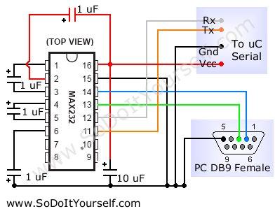
A device that provides a USB port is recognized as a "CP2103 USB to UART Bridge Controller" when connected to a Windows PC. According to the device documentation, it communicates in serial format at 38400 bps. The USB pinout...
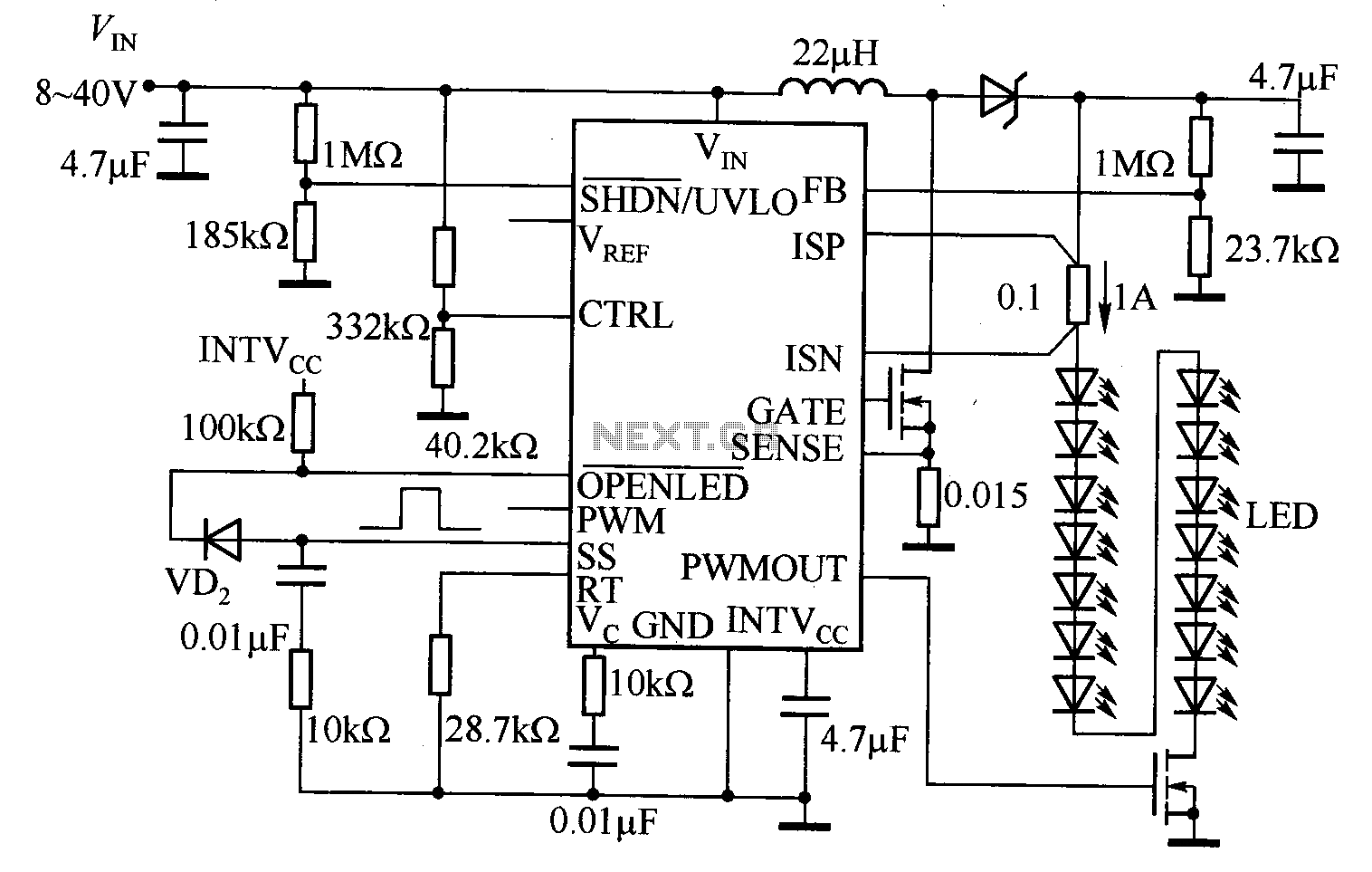
The LT3755 is utilized for high-side current sensing in LED strings, enabling flexible programming and control. It supports a PWM input that allows for a dimming ratio of up to 3000:1, while the CTRL input offers additional analog dimming...
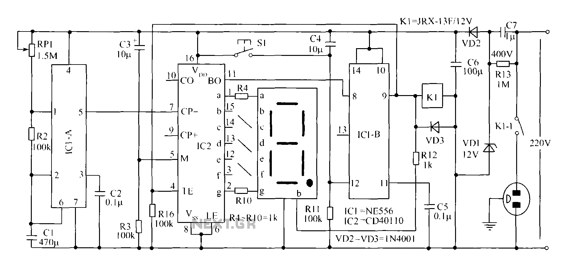
A novel timing switch circuit features a "Variable Timing" adjustment function in addition to a standard timing circuit. It also includes a countdown display feature, which indicates the remaining time of the timing circuit, making it particularly useful. The...
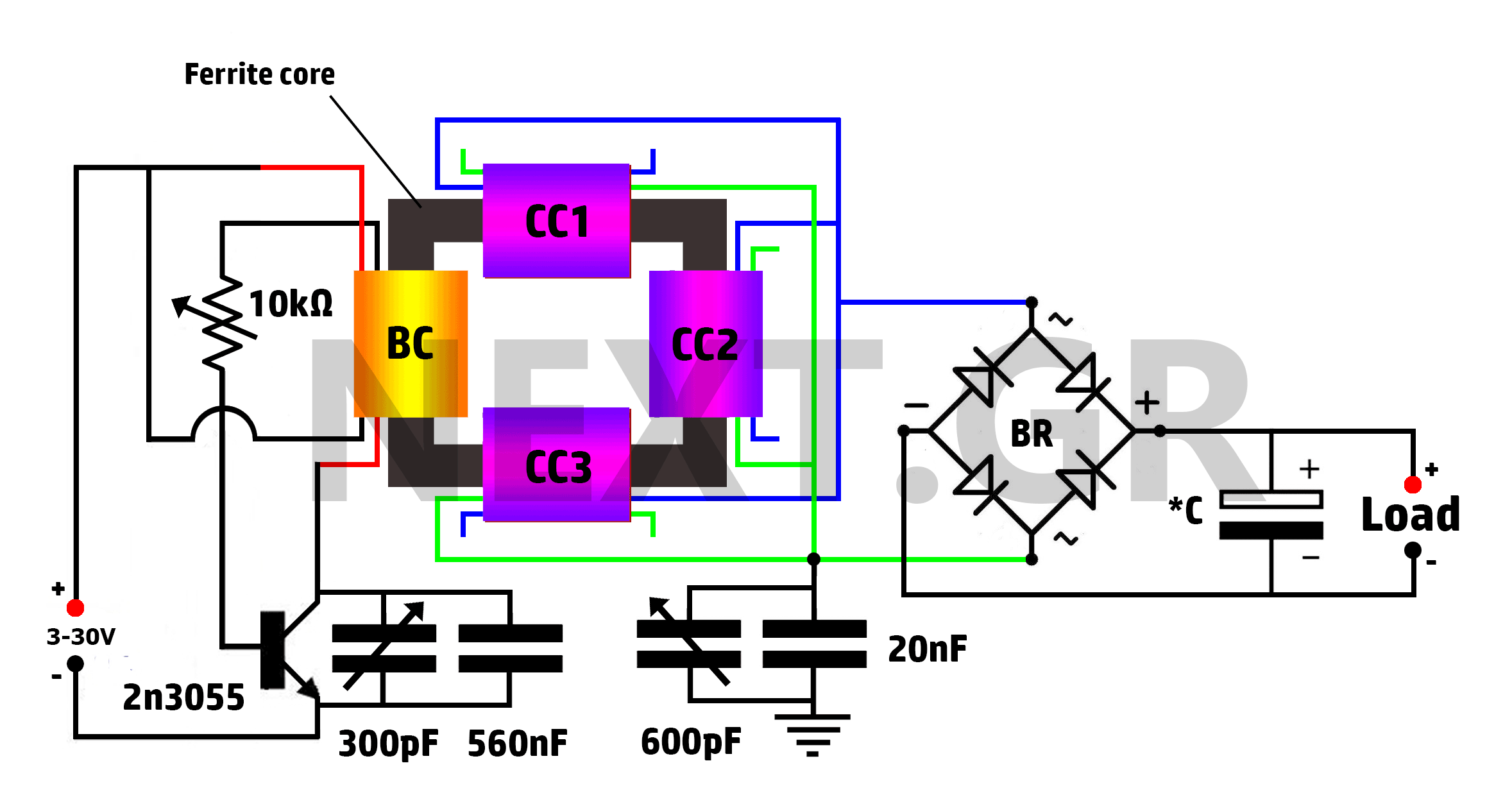
This is a Tesla/joule thief hybrid circuit that its inventor claims can produce 90 times the input power. The circuit can be self-looped and can provide 1050W of power, with only 11.6W looping back to supply the joule thief....
Power Saving Using Time Operated Electrical Appliance Controlling System is a reliable circuit that takes over the task of switching on/off the electrical devices with respect to time. This project replaces the manual switching. It has an inbuilt real-time...