
Cellular phone detector circuit schematic
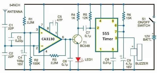
The cellular phone detector circuit is designed to identify the presence of a cellular phone within a specified range. This circuit utilizes basic electronic components, making it accessible for hobbyists and engineers alike. The primary components typically include a radio frequency (RF) receiver, an operational amplifier, and a series of passive components such as resistors and capacitors.
The RF receiver is crucial for detecting the signals emitted by cellular phones. It is tuned to the specific frequency bands used by mobile phones, allowing it to pick up incoming signals effectively. The output of the RF receiver is then fed into an operational amplifier, which amplifies the signal for further processing.
Additional components, such as diodes, may be included to rectify the output signal, converting it from AC to DC. A visual indicator, such as an LED, can be incorporated into the circuit to provide a clear indication when a cellular phone is detected. The LED will illuminate when the circuit receives a sufficient signal strength, indicating the presence of a phone.
This circuit can be powered by a standard battery or a DC power supply, making it versatile for various applications. Overall, the cellular phone detector circuit serves as a practical tool for monitoring cellular phone activity in specific environments, such as classrooms or meeting rooms. Its simplicity and reliance on commonly available electronic parts make it an excellent project for those interested in RF technology and circuit design.Cellular phone detector circuit schematic using common electronic parts 🔗 External reference
Related Circuits
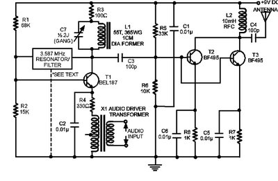
The circuit presented here is a powerful AM transmitter utilizing a ceramic resonator/filter operating at 3.587 MHz. This circuit primarily relies on a transistor for its core functionality. It is possible to use resonators/filters of other frequencies, such as...
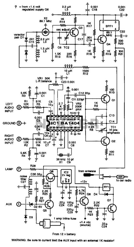
A BA1404 integrated circuit (IC) is utilized to generate a complete FM multiplex (MPX) signal. The chip incorporates all necessary circuitry. Components CI, R3, R4, and C4 are responsible for providing pre-emphasis. The transmitter operates on a single AA...
This is the complete circuit of the modern homodyne receiver. This receiver can receive AM, CW, and SSB transmissions. The modern homodyne receiver is a sophisticated device designed to process various types of radio frequency signals, specifically Amplitude Modulated (AM),...
This is a simple transistor tester circuit that can be utilized to test both NPN and PNP transistors. The voltage source consists of a 6V power supply, which is derived from a step-down transformer that converts 230V AC to...
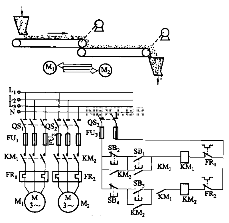
The circuit depicted in Figure 3-86 utilizes a line utilization time relay to control two motors, starting one before the other after an initial stall. The time relay KTi can be adjusted to modify the starting interval of the...
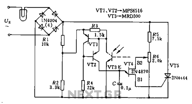
The circuit utilizes a thyristor-based AC automatic voltage regulator to stabilize the brightness of lamp L. A diagonal line connects the thyristor to the T5 bridge. The trigger pulse for the thyristor is generated by a single-junction transistor, VT4....
Warning: include(partials/cookie-banner.php): Failed to open stream: Permission denied in /var/www/html/nextgr/view-circuit.php on line 713
Warning: include(): Failed opening 'partials/cookie-banner.php' for inclusion (include_path='.:/usr/share/php') in /var/www/html/nextgr/view-circuit.php on line 713