
Modern Homodyne reciever circuit
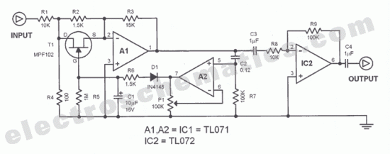
The modern homodyne receiver is a sophisticated device designed to process various types of radio frequency signals, specifically Amplitude Modulated (AM), Continuous Wave (CW), and Single Sideband (SSB) transmissions. The circuit typically consists of several key components, including an RF input stage, a local oscillator, a mixer, an intermediate frequency (IF) stage, and a demodulator.
The RF input stage is responsible for capturing incoming signals from the antenna. It often includes a bandpass filter to ensure that only signals within the desired frequency range are allowed to pass through, minimizing interference from unwanted signals.
The local oscillator generates a signal at a specific frequency that is mixed with the incoming RF signal. This mixing process occurs in the mixer stage, where the two signals combine to produce sum and difference frequencies. The desired output is typically the difference frequency, which corresponds to the intermediate frequency (IF) used for further processing.
The IF stage amplifies the mixed signal, which is then filtered to remove any unwanted frequencies, ensuring that only the desired signal is passed on to the next stage. This amplification is crucial for improving the signal-to-noise ratio, allowing for better performance in receiving weak signals.
Finally, the demodulator extracts the original information from the modulated carrier wave. For AM signals, this involves envelope detection, while SSB signals require more complex processing techniques, such as coherent detection or phase-locked loops, to accurately recover the transmitted audio or data.
Overall, the modern homodyne receiver's design allows for efficient and versatile reception of various modulation schemes, making it a valuable tool in communications and radio technology.This is the complete circuit of the modern homodyne receiver. This receiver can receive AM CW and SSB transmissions. 🔗 External reference
Related Circuits
The function of this automatic volume control circuit is to amplify signals without distorting their dynamic compression. The amplitude differences in the signal are leveled off, eliminating disturbing effects. This technique avoids overcompensation in volume. The circuit is utilized...
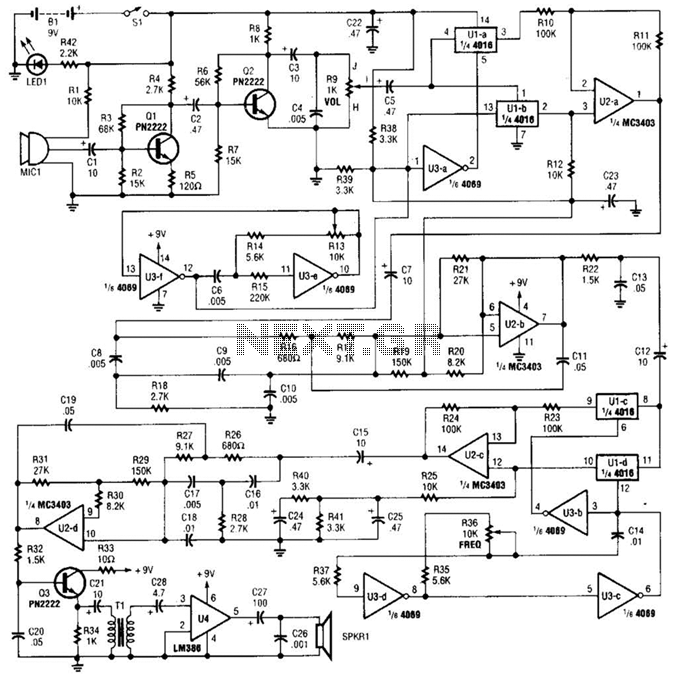
A complete schematic diagram of the voice disguiser is presented. Microphone MIC1 captures the voice signal and transmits it to an audio amplifier, which consists of Q1 and Q2, along with several supporting components. This amplifier features a low-pass...
PC parallel port can be very useful I/O channel for connecting your own circuits to PC. The PC's parallel port can be used to perform some very amusing hardware interfacing experiments. The port is very easy to use when...
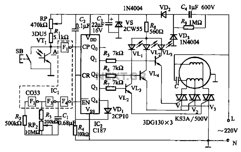
The circuit depicted in Figure 3-5 can be controlled manually using button SB or automatically via light detection using phototransistor VTj. When light from a flashlight is detected by phototransistor VTj, the fan will activate, adjusting its speed automatically...
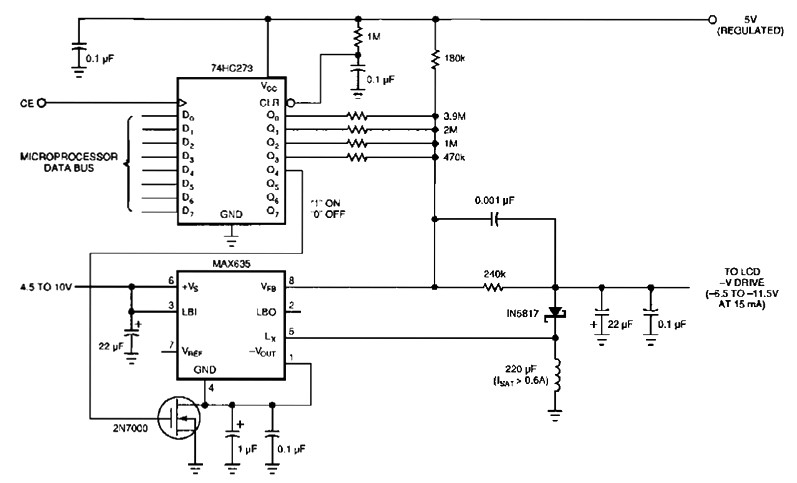
The following figure's switching regulator generates a negative voltage from the notebook battery supply. The microprocessor data bus drives a 4-bit DAC (74HC273), which can vary the regulator output between 6.5 to 11.5 V. This arrangement enables a staircase...
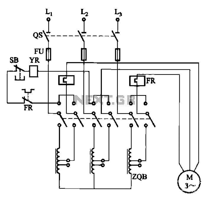
The circuit illustrated in Figure 3-47 involves a three-phase AC motor that is initially connected through a step-down autotransformer. To initiate operation, the power switch is closed, and the operating handle is pushed to the start position. Once the...
Warning: include(partials/cookie-banner.php): Failed to open stream: Permission denied in /var/www/html/nextgr/view-circuit.php on line 713
Warning: include(): Failed opening 'partials/cookie-banner.php' for inclusion (include_path='.:/usr/share/php') in /var/www/html/nextgr/view-circuit.php on line 713