
Cellular Rotary Phone

A PIC 16LF88 microcontroller is used to interpret the hook and rotary signals, employing a straightforward switch decoding routine. The microcontroller detects the opening and closing of two sets of paddles behind the rotary dial. One set of paddles corresponds to each number dialed, while the other set indicates when the rotary dial returns to the home position after dialing a number. The microcontroller incorporates a four-second timeout to accommodate various phone number lengths, enabling dialing of numbers such as 911, 3035551234, and 011212465748.
The ringer circuit operates on the nominal 3.7VDC from the battery, generating approximately 80VAC to activate the hammer mechanism between the two gongs. This task is achieved using a basic DC-to-DC step-up integrated circuit that elevates the DC voltage to around 60V. This 60V is then alternated through an H-Bridge to produce approximately 110VAC. While functional, the DC-DC boost circuit cannot sustain high voltage for extended periods, which is acceptable since ringing only requires a brief activation. The ringer circuit consumes significant power in standby mode, drawing approximately 150mA; therefore, a p-channel MOSFET is employed to power cycle the ringer sub-board, ensuring it receives no power when not in use.
The handset microphone and earpiece are connected directly to the GM862 without additional components. The microphone is biased through a 10k resistor using the 3.7V from the battery. Despite the expectation of a clean DC power source from a high-current battery, significant buzzing is present in the earpiece. Disconnecting the microphone eliminates the buzzing. An electret microphone biasing circuit is utilized to provide the necessary current for operation. This circuit takes the 3.8V main power and outputs a clean 3V for microphone biasing, effectively reducing RF noise from the GM862. A basic 3.3V regulator and capacitors are also employed to achieve similar results. Although powering the microphone directly with the main voltage is possible, it is likely to produce buzzing. To mitigate this issue, routing the main voltage through a simple 3V or 3.3V regulator circuit is recommended.
The PIC microcontroller is connected to the GM862 in multiple ways, requiring TX and RX lines for command transmission and response reception. Additionally, the PIC monitors the RI (Ring Indicator) line and controls the On/Off line to activate the GM862 with a 1-2 second pulse when the board is powered on. The PIC also manages the p-channel MOSFET to control the external ringer circuit.This is a deeper look into the Port-O-Rotary phone. We stuck the GM862 cellular module into an old rotary phone enclosure, and voila, it was an instant, ridiculous, hit. Really simple - the GM862 requires 3. 8V and a Lithium Polymer outputs 3. 7-4V. No regulator needed, but we will need a charger. We currently use an external charger from a third pa rty company. Aubrey noted the GM862 has a built in Lithium-Ion charger that may work, we haven`t tested it yet. Ideally we would stick a barrel jack in the back of the enclosure where the RJ11 telephone jack used to reside. Anyone have any recommendations I have used the charging circuit in the GSM862 on the exact LIPO batteries you use and it works good, it takes forever to charge.
NOTE: You must connect a low esr cap to the battery if you are using the internal charger. We use a 100uF 6. 3v cap in our design, Digikey part# 493-2309-1-ND. We use a PIC 16LF88 (remember we are at 3. 7V! We need a low-voltage PIC!) to read the hook and rotary. Pretty simple switch decoding routine. We just read the opening/closing of the paddles behind the rotary. There are two - one set of paddles opens and closes for each number that passes by, the other set of paddles is normally open when the rotary is in the home position and closed while the rotary dial is moving. Reading this second set of paddles will tell us when the dialing of a single number is complete. Finally, because we don`t know how long of a number the user is dialing, the PIC waits for a 4 second timeout before sending the given phone number to the GM862.
This way the user can dial any type number of any length: 911, 3035551234, and 011212465748. The ringer circuit must use the 3. 7VDC nominal from the battery and output ~80VAC to get the coil to kick the hammer between the two gongs. Tricky to say the least. Pete Dokter (mad genious) used a basic DC-to-DC step up IC to get the DC voltage up to a weak 60V. This 60V was then alternated through an H-Bridge to get ~110VAC. It works! But the DC-DC boost circuit can`t sustain the high voltage for more than a few seconds - just about perfect because we just need to ring the bells for a second or two and then pause between rings.
The ringer circuit is a bit power hungry in stand-by (using ~150mA in standby!), so we use a p-channel MOSFET to power cycle the ringer sub-board. When the phone ain`t ringing, the ringer board gets no power. We hooked the handset mic and ear-piece directly to the GM862 without any external components. The mic was biased through a 10k resistor using the 3. 7V off the battery. One would think that this would be a clean source of DC power, coming directly off a high current battery.
In practice however, there is some horrendous buzzing in the ear piece. Funny thing, when we disconnect the mic, all the buzzing went away. Here you can see a mildly complex electret mic biasing circuit. What is this Well, an electric mic needs just a little bit of current to operate. Normally you can power the mic by just attaching one side to a 10k pull-up resistor. This circuit takes the 3. 8V main power, and outputs a super clean 3V to biasing the mic. Perhaps getting rid of all the RF noise that the GM862 is putting onto the main power No way! REALLY! It works great. Why didn`t we think of this before! We use a basic 3. 3V regulator and a couple caps and it works just as well. You can power the mic using the main 3. 8V power, but expect some buzzing. To get rid of the buzzing, send that main voltage through a simple 3V or 3. 3V regulator circuit and you`ll be very happy. The PIC is connected to GM862 in various ways. Obviously we need TX and RX to send commands and receive OK responses. The PIC also monitors the RI (Ring indicator) line, as well as controlling the On/Off line to turn on the GM862 (requires a 1-2 second pulse) when the board is powered up. The PIC controls the p-channel MOSFET to power the external ringe 🔗 External reference
Related Circuits
The signal from a microphone is too weak for a standard line input. This low-noise DC-coupled microphone amplifier provides a solution for anyone who wants to connect a microphone to a high-fidelity installation. As shown in the schematic diagram,...
Circuit to close a relay when any phone extension is off-hook. Voltage at the gate of the MOSFET should be negative (1-3 volts) with respect to the source when phones are on-hook. Voltage at the gate should be positive...

By mixing an audio signal with ultrasound, it is possible to perceive the audio as if it originates from within the head, even when the 'headphones' are positioned far from the ears. Patrick Flanagan invented the "Neurophone" over 40...
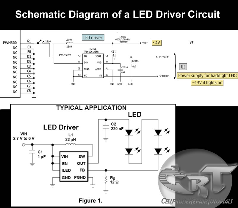
An LED (light-emitting diode) is utilized to illuminate keypad keys and LCD screen displays on all mobile phone handsets. It is controlled by the voltage or current drawn at its terminals. In the schematic diagram, the LEDs are driven...
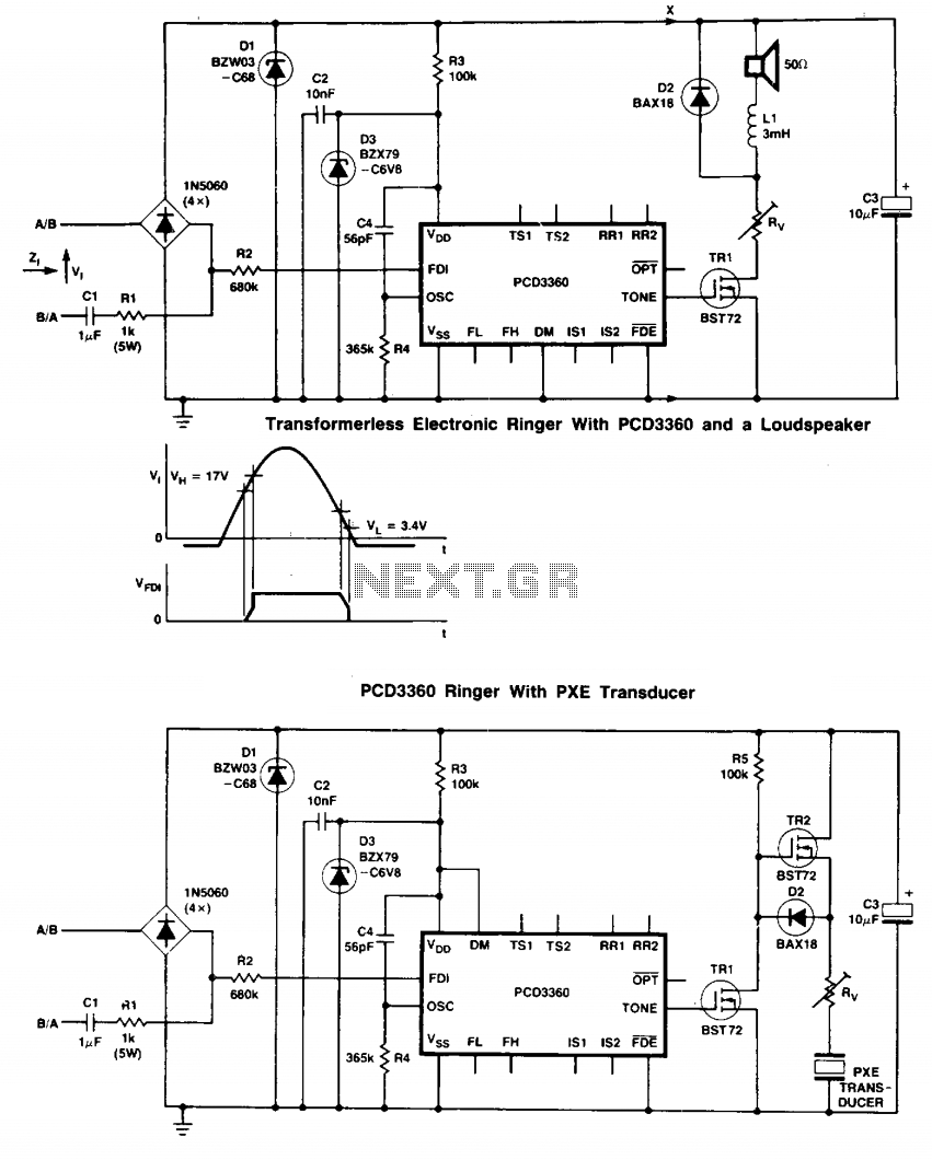
Two BST72 transistors provide an output voltage swing almost equal to the voltage at C3. Pins IS1 and IS2 are inoperative because DM = HIGH. Volume control is possible using resistor Rv. The circuit utilizes two BST72 transistors configured to...
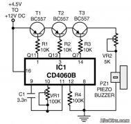
This is a simple home telephone ringtone generator circuit constructed using only a few electronic components. It generates a simulated telephone ringtone and requires a DC supply voltage ranging from 4.5V to 12V. This circuit can be used in...