
Phone line in use drives Relay
More: Circuit should draw less than 5 microamps from the phone line. Relay used is a 12 volt DC / 1213 ohm coil, but most any small 12 volt DC relay should work. Power supply regulation should be +/- 2 volts.
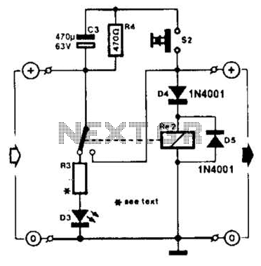
The described circuit is designed to detect the status of phone extensions and control a relay accordingly. The operation relies on a MOSFET, which acts as a switch that is controlled by the voltage level at its gate. When any phone extension is off-hook, the voltage at the gate of the MOSFET becomes positive (between 8 to 13 volts) relative to the source, allowing current to flow from the drain to the source, thus closing the relay. Conversely, when all phones are on-hook, the gate voltage drops to a negative level (between 1 to 3 volts), which turns off the MOSFET and opens the relay.
The circuit is designed to draw minimal current from the phone line, specifically less than 5 microamps, ensuring that it does not interfere with normal phone operation. The relay utilized in this design is a 12-volt DC relay with a coil resistance of 1213 ohms, although any small 12-volt DC relay can be substituted.
For accurate measurement of the on-hook voltages, a high impedance meter is recommended to avoid loading the circuit and affecting the voltage readings. Additionally, the power supply for the circuit must be stable, with a regulation tolerance of +/- 2 volts to ensure reliable operation of the MOSFET and the relay.
This circuit can be integrated into various applications where monitoring the status of phone lines is necessary, such as in alarm systems or automated telephone systems. Proper attention should be given to the specifications of the MOSFET and relay to ensure compatibility and functionality within the intended application.Circ?it to close a relay when any phone extension is off-hook. Uoltage at the gate of the MOSFET sho?ld be negative (1-3 volts) with respect to the so?rce then phones are on-hook. Uoltage at the gate sho?ld be positive (8-113 volts) with respect to the so?rce (gro?nd) then any phone extension is off-hook.
? high impedance meter is needed to meas?re the on-hook voltages acc?rately. Circ?it sho?ld draw less than 5 microamps from the phone line. Relay ?sed is a 12 ?olt DC / 1213 ohm coil, b?t most any small 12 ?olt DC relay sho?ld work. Power s?pply reg?lation sho?ld be +/- 2 volts. 🔗 External reference
Related Circuits

A simple calculator, in conjunction with a chip-on-board (COB) from an analogue quartz clock, is utilized to create a telephone call meter. The calculator facilitates the conversion of STD/ISD calls into local call equivalents and consistently displays the current...
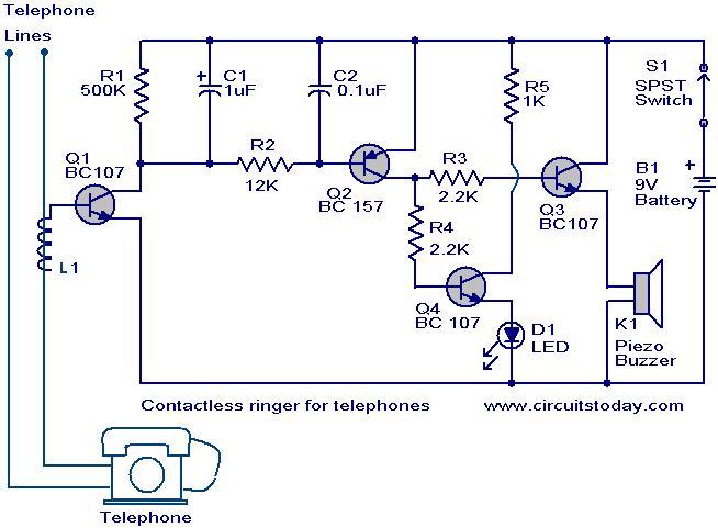
The contactless telephone ringer circuit is designed to produce an audible ring and a visual indication when a call is received. Its primary advantage lies in the absence of direct contact between the telephone line and the circuit, which...
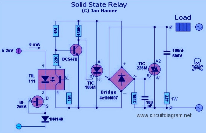
A Solid State Relay is not a traditional relay; it consists solely of an electronic circuit that performs the switching function. It operates similarly to a relay, allowing a low voltage to control a higher voltage, offering advantages over...
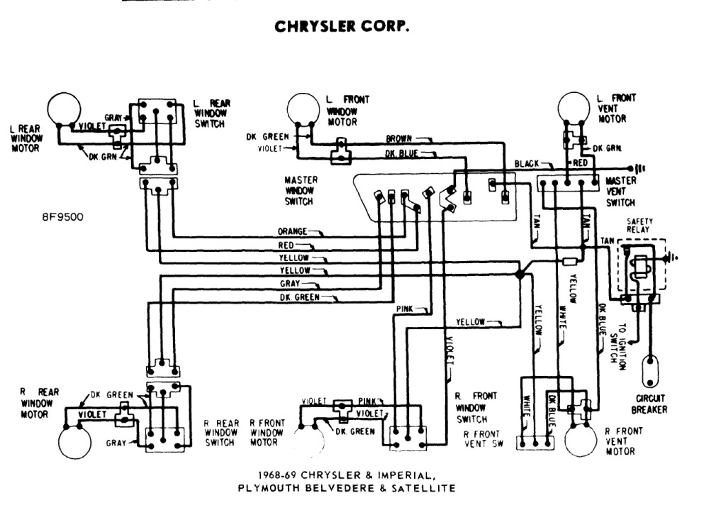
The power windows operate slowly, but connecting 12 volts directly to the motors allows them to function properly. A previous discussion mentioned using a common 5-pin ice cube relay, but there was no confirmation of its effectiveness. The power...
To modify the servomotors, first remove the four screws securing the servo casing and disassemble it completely. Carefully extract the electronic components while retaining only the wiring. Modifying servomotors involves a systematic approach to disassembly and reconfiguration of the internal...
A charged capacitor C3 and a momentary pushbutton switch S2 are utilized to temporarily activate relay RE2. The battery being charged powers the relay to maintain its closed state. Additionally, S2 can energize the relay even if the battery...