
How Do LED light bulbs works on Mobile Phone Circuit

The LED circuit in mobile phones is a critical component for user interaction and visual feedback. The LED driver chip is specifically designed to manage the power requirements of the LEDs efficiently. It utilizes a boost converter topology to increase the input voltage from the battery to the necessary level for driving the LEDs. This ensures that the LEDs can operate at their optimal brightness without drawing excessive current that could lead to overheating or damage.
The PWM signal generated by the switching control circuit is essential for dimming the LEDs. By varying the duty cycle of the PWM signal, the effective voltage seen by the LEDs can be adjusted, allowing for smooth transitions between different brightness levels. This capability is particularly useful in applications where ambient light conditions may change, requiring the LED brightness to adapt accordingly.
The integration of overvoltage and short circuit protection mechanisms within the LED driver chip enhances the reliability of the mobile phone. These features prevent damage under fault conditions, ensuring that the device remains functional even if an LED fails or if there is an unexpected load on the circuit.
The communication between the application processor and the LED driver is typically achieved through a serial interface, enabling the CPU to send commands that dictate the behavior of the LEDs. This level of control allows for advanced features such as notifications, alerts, and visual effects that enhance the user experience.
In summary, the LED circuit within mobile phones is a sophisticated system that combines various electronic components to provide illumination and visual feedback. The design considerations for safety, efficiency, and user interaction are paramount in ensuring the longevity and functionality of mobile devices.An LED - light emitting diode is used to illuminate keypads keys and LCD screen displays on all mobile phones handsets. It is being controlled by a voltage or current draws on its terminal leds. On schematic diagram we notice that the LEDs is driven by an LED driver chip`s, and an Switching Control circuit that also being packed in a chip.
The LED driver is being used to stabilized the voltage and current and do take control on engaging ON and OFF status of an LEDs to light up or not. The Switching control circuit feeds and release a Pulse Width Modulation Signal (PWM) to switch and light up the LEDs light bulbs.
A pulse width modulation signal is a type of digital frequency signal range up to 1khz to enable and implement to take control of LED brightness. Once that certain signal is being received by the LED driver, the LED driver now will engage and release the voltage or current that being feeds up from the mobile phones battery supply voltage; LED drivers is a high frequency, synchronous boost converter with constant current output to drive up to 5 white LEDs.
This device circuit is designed for maximum safety, it integrates overvoltage and short circuit protection when the output is being shorted to the ground. Meaning this chips circuitry will not easily breakdown for it is designed to protect when short circuit happens.
In mobile phones application methods; the switching control circuit that release pulse switching signal is also being synchronized programmed by the the application processor (CPU) to engaged a full control on how and which proper situation that the LED will be switch to light up or not. The above image is an example of the LED circuit, how those particular stages and components being mounted on a phones circuits.
Note that the LED driver and switching control circuits is being packed into an Integrated Circuit or ICs. To all beginners: A bunch of simplified STEP By STEP Procedures On Troubleshooting LED Problem issues on various mobile phones product will be Posted Here Later.
Just keep on visiting this blog more often. 🔗 External reference
Related Circuits
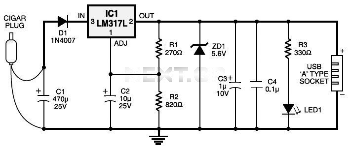
Currently, nearly all computer systems include logic blocks designed for interfacing with a USB port. In practical terms, a USB port can provide more than 100 mA of continuous electric current at 5V to the peripherals connected to the...
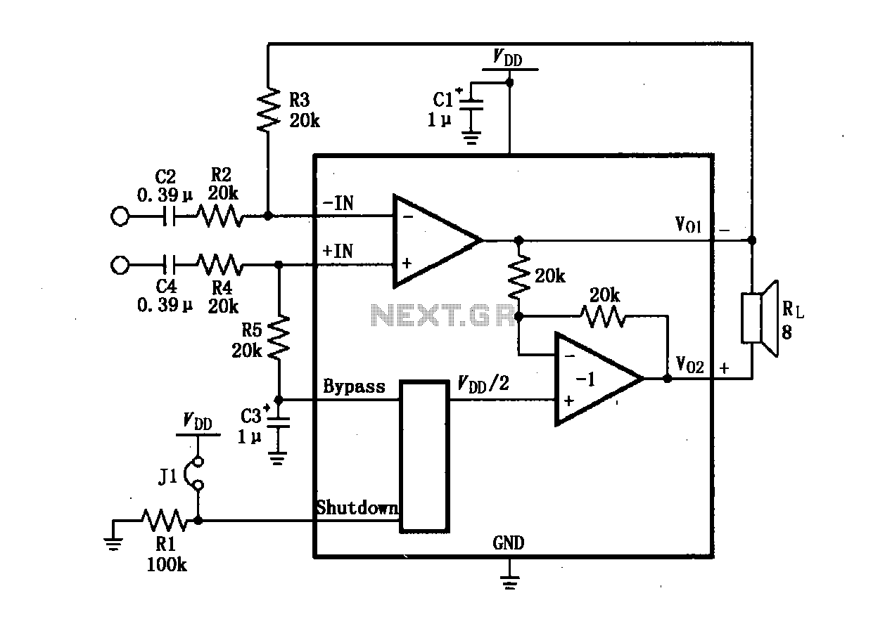
The LM4904 audio input differential amplifier circuit is presented. The audio signal is provided as a differential input to the +IN and -IN terminals. The LM4904 is a low-power audio input differential amplifier designed for high-performance audio applications. This circuit...
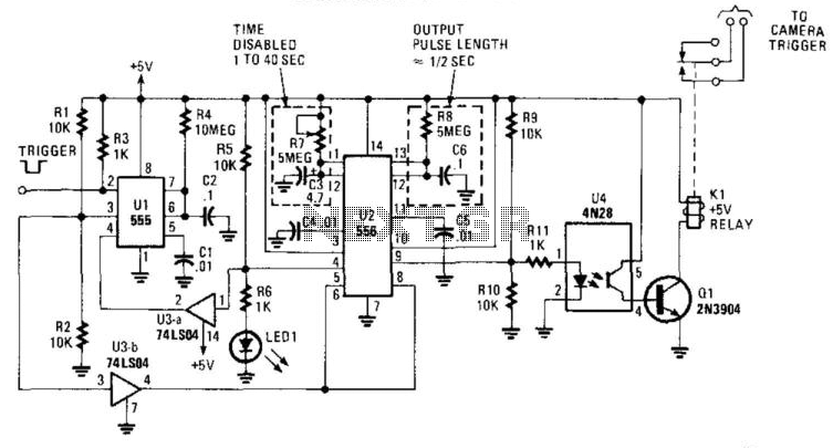
This circuit is designed to activate a camera shutter. Grounding pin 2 of U1 causes pin 4 of U1 to go high, which triggers both timers of the dual timer U1. One output maintains the reset (pin 4) of...
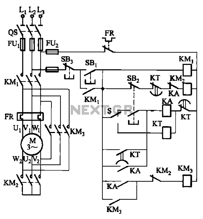
The circuit is depicted. It is capable of both manual and automatic control. The circuit in question is designed to facilitate dual modes of operation: manual and automatic control. This versatility allows users to engage with the system according to...
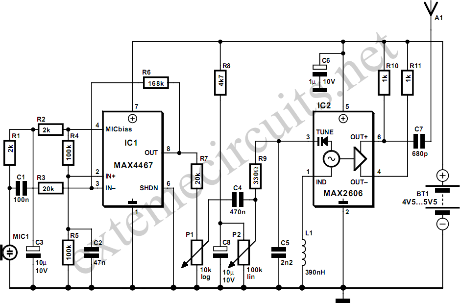
This project is a simple, inexpensive, and engaging circuit designed for home experimenters or hobbyists. It functions as a basic transmitter capable of transmitting speech over a short distance, effectively serving as a cordless microphone. The circuit employs two...
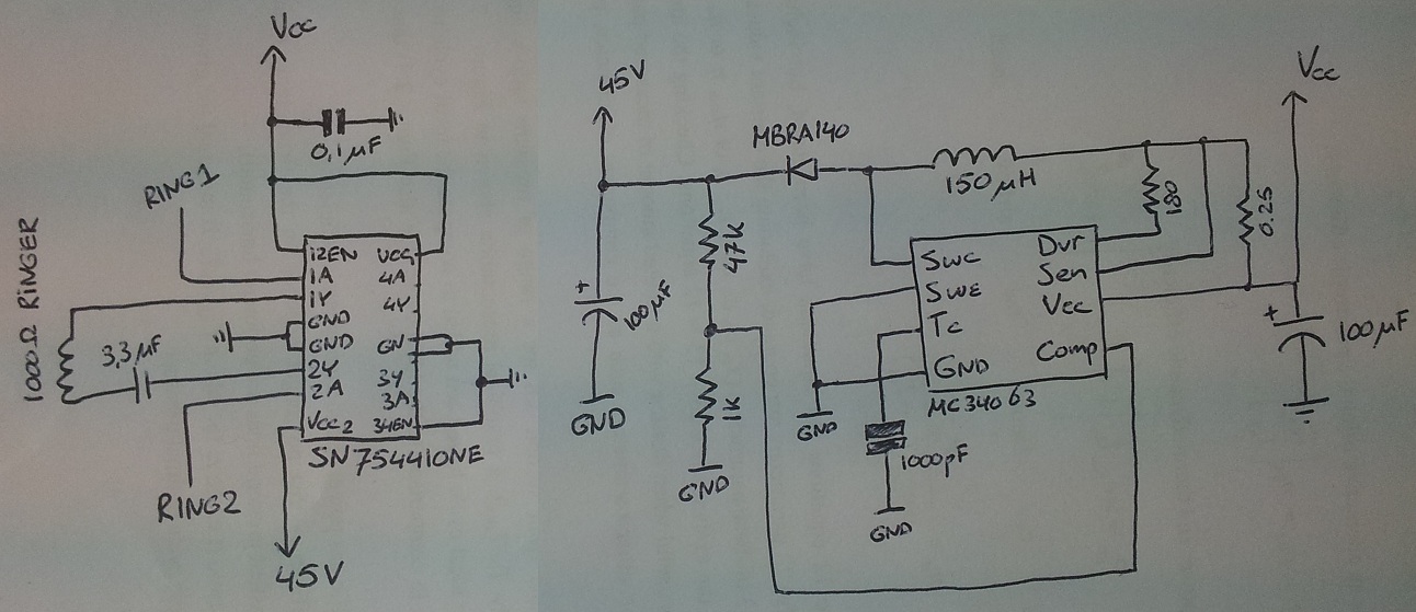
The process involves adapting an old phone for Bluetooth functionality, specifically testing the ringer circuit constructed using schematics from Sparkfun. When connecting a section of the schematic to a 3.5V source (Vcc), an output voltage of 45V is observed,...