
CENTER TAPPED TRANSFORMER AUDIO OSCILLATOR

The described oscillator circuit is a fundamental design often used in audio applications, where modulation of sound frequencies is required. The center-tapped transformer plays a critical role in this configuration, as it not only provides the necessary load for the transistor but also facilitates the feedback loop essential for sustaining oscillation. The feedback signal is vital for maintaining the oscillation frequency and stability of the circuit.
In this setup, the transistor Q1 acts as the primary amplifying element. The DC bias provided by R1 ensures that Q1 operates in the active region, allowing it to amplify the AC signals effectively. The value of R1 is crucial; if it is too low, it risks pushing Q1 into saturation, leading to distortion or complete cutoff of the output signal. Conversely, if R1 is too high, the transistor may not turn on sufficiently, resulting in weak oscillation.
Capacitor C1 serves to couple the AC signal from the transformer to the base of Q1. The capacitance value of C1 can be adjusted to fine-tune the frequency response of the oscillator. A larger capacitance will allow lower frequencies to pass through, potentially lowering the tone, while a smaller capacitance will restrict lower frequencies and allow higher frequencies to dominate.
The transformer’s output is connected to the speaker, which converts the electrical oscillations into audible sound waves. By modifying the values of R1 and C1, the user can experiment with different sound characteristics, such as volume and tonal quality, making this circuit versatile for various audio applications.
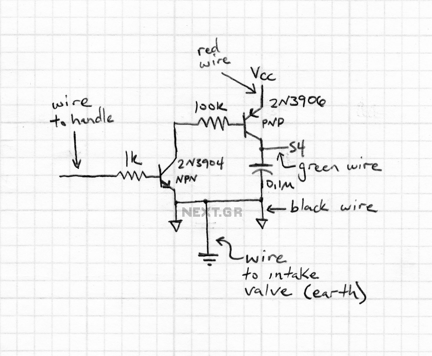
In summary, the oscillator circuit's design, with its center-tapped transformer, biasing resistor, and coupling capacitor, allows for a range of sound modulation possibilities, while careful consideration of component values ensures reliable operation without risking damage to the transistor.The oscillator circuit uses a center-tapped transistor output transformer to serve as a load for the collector of Q1, supply a feedback signal for the base, and serve as the output winding for driving the speaker. R1 supplies dc bias and C1 completes the ac path from the transformer to Q1`s base. You can play around with the values of C1 and R1 to change the oscillator`s output level and tone, but don`t reduce R1`s value too much or the transistor will draw excessive collector current. 🔗 External reference
Related Circuits
Construct the Colpitts oscillator using either a breadboard (prototype board) or stripboard, and then verify its operation with a multimeter and oscilloscope. This Colpitts oscillator generates a sine wave output exceeding 12V peak-to-peak at a frequency determined by the...
Designed for communications use, this equalizer circuit utilizes a Mitsubishi M5226P audio equalizer IC to modify frequency response. It operates with a supply voltage ranging from 9 to 20 V. Capacitors C6 through C16 are polyester film capacitors with...
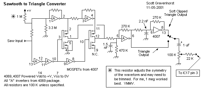
This wave shaper needs an input saw that goes from Vss to (ideally) Vdd. It works well with the 4069 VCO designed by Ren? Schmitz. Any saw will work as long as the wave is centered halfway between the...
The circuit was designed to operate a frequency modulation voice transmitter over the FM band within the VHF frequency range. The transmitter is an electronic device. The frequency modulation (FM) voice transmitter circuit operates within the VHF (Very High Frequency)...
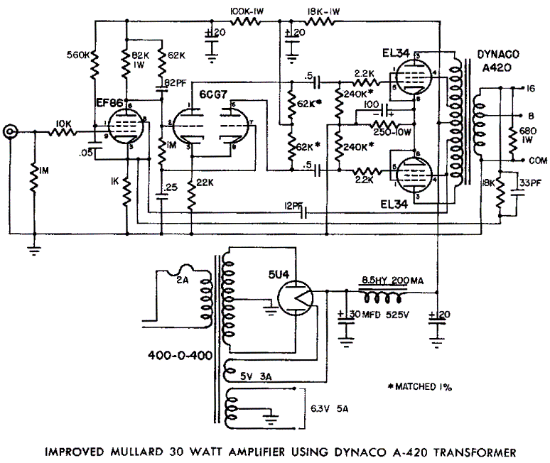
Mullard EL34 push-pull vacuum tube amplifier schematic using Dynaco A420 audio output transformers The Mullard EL34 push-pull vacuum tube amplifier is a classic audio amplification circuit that utilizes EL34 vacuum tubes in a push-pull configuration to deliver high-quality sound reproduction....
The purpose of this experiment is to explore the properties of a nonlinear circuit that closely resembles a driven pendulum. This serves as an excellent introduction to nonlinear phenomena, including period doubling and chaos. The circuit presented is an...