
central locking interface
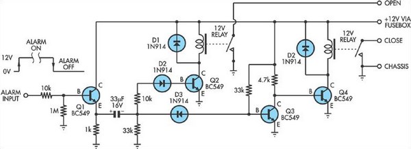
To implement the described functionality, a relay interface circuit can be designed to interface between the car alarm and the central locking system. The circuit will require two relays rated for the appropriate voltage and current to handle the solenoid activation of the central locking mechanism.
The first step involves identifying the alarm signal output, which is typically a wire leading from the alarm control unit. This signal should be monitored to determine its state (high or low). A microcontroller or a simple transistor circuit can be employed to detect the state of the alarm signal. When the alarm is activated (high state), the microcontroller or transistor will trigger the relay circuit.
The relay circuit consists of two relays, each capable of handling the current required by the central locking system. The relays should be connected in parallel, ensuring redundancy and reliability. The contacts of these relays will be wired to the master solenoid of the central locking system.
To convert the toggle of the alarm signal into a brief pulse, a monostable multivibrator (such as a 555 timer configured in monostable mode) can be used. This component will generate a short pulse each time the alarm signal toggles, ensuring that the relays are activated momentarily to engage the locking mechanism without causing continuous activation.
Additional components such as diodes should be included in the circuit to protect against back EMF generated by the relays when they are deactivated. Proper power supply decoupling and filtering should also be implemented to ensure stable operation of the microcontroller or transistor circuit.
The overall design will ensure that the car alarm can effectively control the central locking system, providing enhanced security and convenience for the vehicle owner.Some cheap car alarms do not have a connection for the central locking system. However, in most it should be possible to find a point in the alarm circuit which is high when the alarm is activated and low when it is off. This signal can then be used to drive this relay circuit to operate the central locking system. The interface circuit converts e ach toggle of the alarm signal to a brief pulse to operate the two relays which then are then connected in parallel with appropriate contacts on the master solenoid in the central locking system. 🔗 External reference
Related Circuits
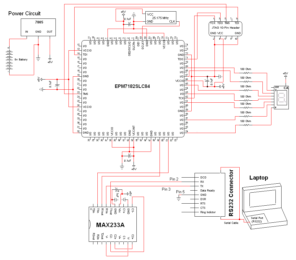
The schematic for this project is a modified version of the CPLD development board schematic. Several new components have been added for this project, and the completed schematic can be viewed below. The main components in the schematic are...

An application circuit for a biaxial magnetic field sensor is presented. This circuit utilizes the HMC1002 biaxial magnetic sensor along with two AMP04 amplifiers (A1, A2) to simultaneously measure magnetic fields in both the X-axis and Y-axis directions. The...
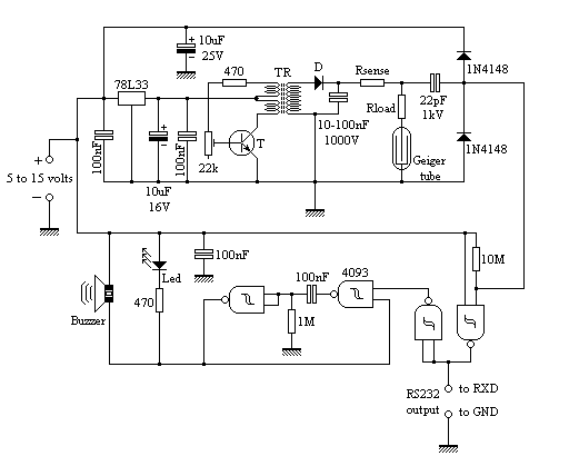
The circuit employs common building blocks. The high-voltage power supply is a classical oscillator circuit utilized in various applications where low current and high voltage are required. The transformer (TR) is a step-up transformer salvaged from a xenon light...

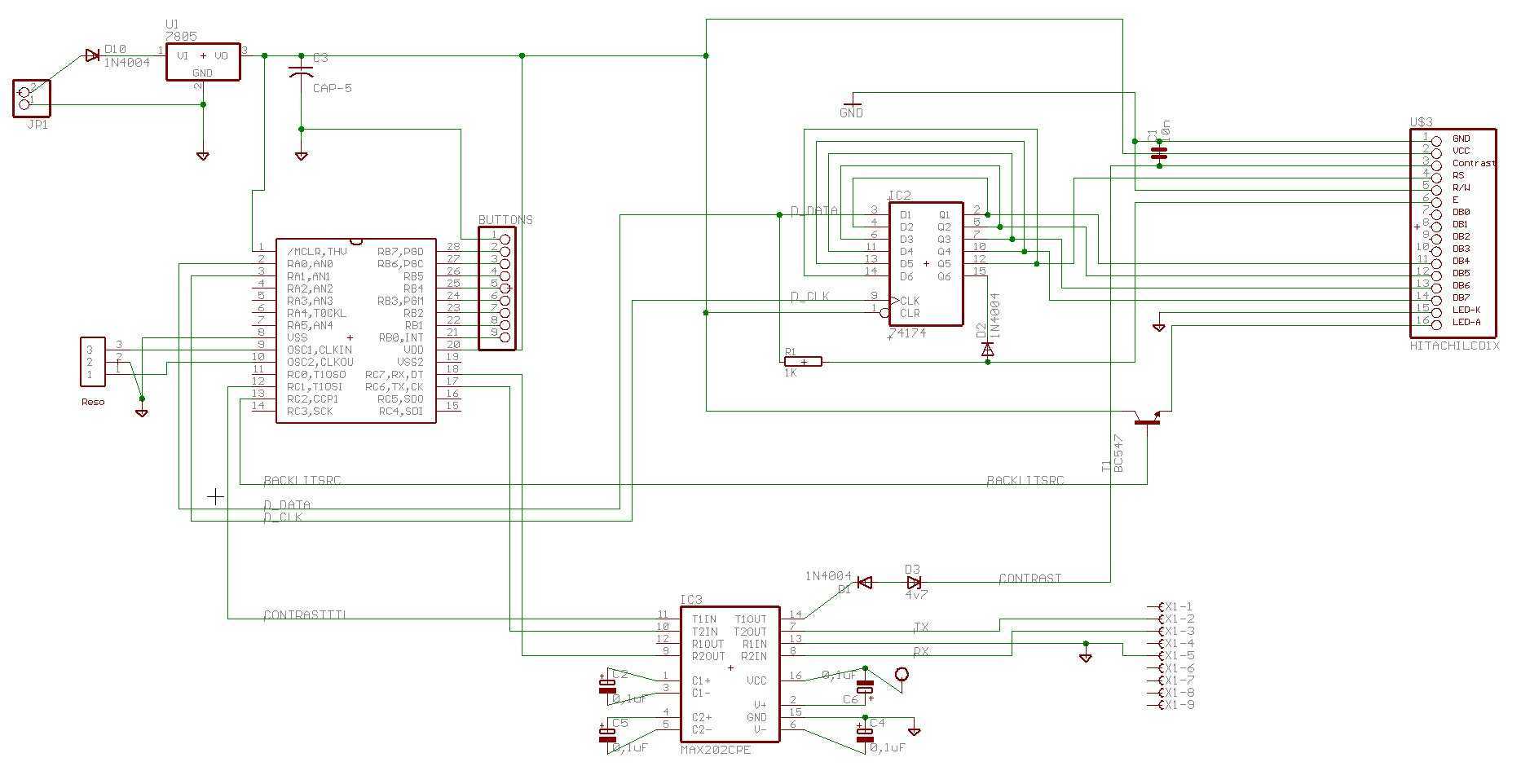
An LCD (liquid crystal display) is an electronically modulated optical device composed of multiple pixels filled with liquid crystals, arranged in front of a light source (backlight) or reflector to generate images in either color or monochrome. The block...
There is enough of poorly constructed RS232 alike TTL level interfaces (+5volt), this one generates its own +/- 10..11 volts as RS232 specs require, and is able to use very long cables like RS232 can, and protects computer as...
Below are three examples of controlling a relay from the PC's parallel printer port (LPT1 or LPT2). Figure A shows a solid state relay controlled by one of the parallel port data lines (D0-D7) using a 300 ohm resistor...