
Magnetic field sensors circuit and serial interface application HMC1002

The application circuit for the biaxial magnetic field sensor is designed to accurately capture and process magnetic field measurements in two dimensions. The HMC1002 sensor is the central component, capable of detecting magnetic fields along the X and Y axes. The integration of two AMP04 operational amplifiers allows for the amplification of the sensor's output signals, ensuring that the signals are strong enough for further processing.
The amplified signals from the AMP04 devices are directed to a 12-bit analog-to-digital converter (ADC), specifically the TLC2543. This ADC converts the analog voltage signals into digital data, which can then be processed by a microcontroller or other digital processing unit. The interface circuit ensures proper communication between the ADC and the processing unit, facilitating seamless data transfer.
Power management in the circuit is handled by the MAX662A DC/DC converter, which efficiently steps up the input voltage from +5V to +10V. This increased voltage is crucial for powering the IRF7105, a pulse current driver that is responsible for generating the necessary input signals for the HMC1002 sensor. The pulse current driver operates by sending specific signals to the sensor, which are essential for its operation and performance.
The design also emphasizes the importance of using tantalum capacitors in the circuit. These capacitors are known for their stability and reliability, making them suitable for applications requiring precise voltage regulation and filtering. Their inclusion in the circuit contributes to the overall performance and accuracy of the sensor system.
Overall, this application circuit offers a robust solution for measuring magnetic fields in two dimensions, utilizing advanced components and careful design considerations to achieve high performance and reliability in various applications.Application Circuit biaxial magnetic field sensor shown. Using a biaxial magnetic sensor HMC1002, two AMP04 (A1, A2), the magnetic field can simultaneously measure the X-axis d irection and the Y-axis direction. HMC1002 two voltage signals outputted respectively after A1 and A2 amplification, then the analog input and the reference terminal 12 bit A/D converter TLC2543, and then connected via the interface circuit P. MAX662A is a highly efficient DC/DC converter can be raised to + 5V power supply + 10V, as the drive power IRF7105.
Pulse current driver input signal from the P, the output is sent to the HMC1002 S/R + terminal (pin 16). Figure C3 tantalum capacitors should be used.
Related Circuits
A circuit is required where, upon power application, a timer triggers, keeping a relay in the off state. Once the timer completes its cycle, the relay will activate. The circuit design consists of a timer integrated with a relay to...
Automatic Gain Control (AGC) is a circuit design that maintains a consistent level of amplification for sound or radio frequency signals. If the signal is too low, the AGC increases the gain to ensure the output remains at a...
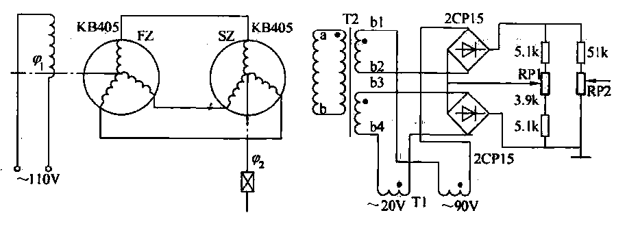
The transmitter (FZ) winding and receiver (SZ) correspond to the three-phase windings connected to a 110V AC voltage supply for transmission. The field winding, early start angle, and receiver output voltage at both ends of the stator windings reflect...
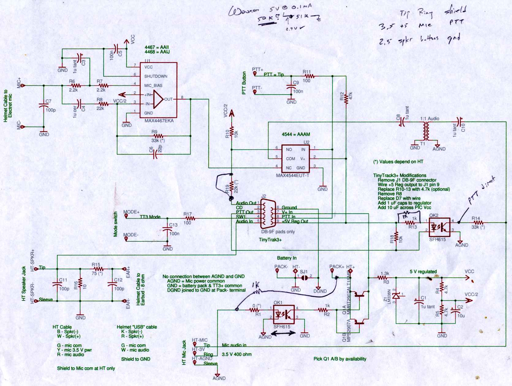
Connect the Byonics TinyTrak 3+ GPS modem, helmet earbud/mic, and external battery pack to the Z-1A, which is incompatible with the Wouxun. The KG-UV3D utilizes the Kenwood HT interface with a single ground for mic, speaker, and PTT functions,...
The motors will be powered by the full source voltage, so it is important to ensure that this does not cause the robot to operate too quickly. The Firebot utilizes GM3 motors powered by a 9V battery; however, in...
Figure A, B, and C illustrate the test rod end clip, with a positive power supply terminating test equipment. The B and C ends are connected in series with the load, where C represents the negative side of the...