
Ceramic Filter Beat Frequency Oscillator

The Beat Frequency Oscillator (BFO) circuit is designed to facilitate the reception of Single Side Band (SSB) and Continuous Wave (CW) transmissions, which are commonly used in amateur radio and other communication systems. The primary function of the BFO is to generate a carrier frequency that combines with the incoming SSB signal. This combination allows for the demodulation of the audio signal that is otherwise missing due to the nature of SSB transmission.
The circuit operates at a fixed frequency of 455 kHz, which is a standard intermediate frequency (IF) used in many radio applications. A ceramic filter is employed in the circuit to ensure that the generated carrier frequency is stable and accurate. The use of a ceramic filter is advantageous due to its low cost, high selectivity, and minimal size, contributing to the overall simplicity of the design.
The RF choke (RFC) is a critical component in this circuit, serving to block RF signals while allowing DC to pass through. It is constructed by winding 150 turns of enamelled wire around a half-watt, 150 kΩ carbon resistor. This configuration provides the necessary inductance to facilitate the operation of the BFO while maintaining a compact form factor.
The simplicity of the BFO circuit is further enhanced by its lack of tuning requirements, which eliminates the need for adjustments during operation. This design feature is particularly beneficial for users who may not have access to sophisticated equipment or expertise in radio frequency tuning. Additionally, the circuit does not require a regulated power supply, making it accessible for various applications, including portable and battery-operated devices.
Overall, the BFO circuit is an effective solution for demodulating SSB and CW signals, providing a straightforward and cost-effective method for enhancing radio communication capabilities.BFO is a simple device which helps us to listen SSB and CW transmissions. Reception of SSB and CW signals requires a product detector or BFO (Beat Frequency Oscillator) to reinsert the missing carrier. This circuit is very simple since it requires no turned circuit and hence no adjustment in the BFO circuit.
The number of components required is also very limited. To produce 455 Khz carrier a ceramic filter is used. It cost me Rs: 6/- only. The RF choke (RFC) is made by winding 150 turns of enamelled wire on half watt 150 K carbon resistor. When receiving Single Side Band (SSB) signals the locally generated carrier beats with the SSB signal to produce the complete audio signal.
Because the ceramic filter operates at fixed frequency, no turning is required to demodulate the single side band (SSB) signals and no regulated power supply is necessary. 🔗 External reference
Related Circuits
Its frequency depends on the capacitance of the vary cap diode. The center frequency is changed by varying the biasing voltage of the vary cap through the 47K pot. You can use a 75cm telescopic antenna or simply a...
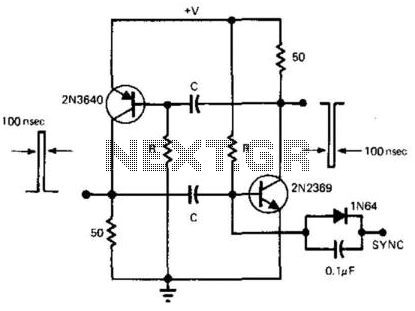
This simple and symmetrical free-running generator has a 50-ohm output impedance, a pulse width of 100 ns, and complementary outputs that swing from ground to the power supply voltage. It operates within a power supply range of less than...
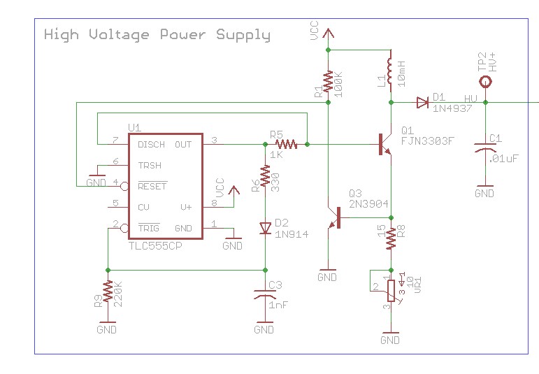
The design involves using a 555 timer as an oscillator in the high voltage power supply section. There is a query regarding the possibility of altering the design to utilize an output from a microcontroller to generate an oscillating...

It has been determined that the Hijack method for obtaining serial data from the Mindflex to the iPhone will likely not be utilized. This decision is primarily based on the availability of most components needed to construct a similar...
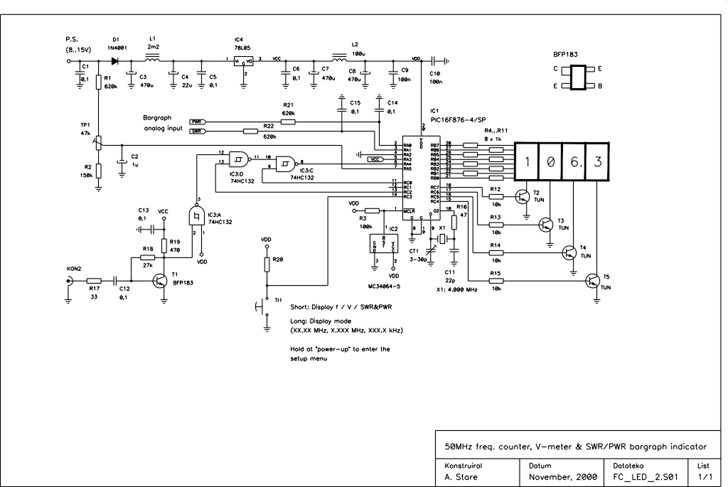
This device is an upgraded version of the PIC16C71 4-digit LED frequency counter and voltmeter. It eliminates several hard-to-find components from the previous model, which have been out of production for some time. The older PIC16C71 has been replaced...
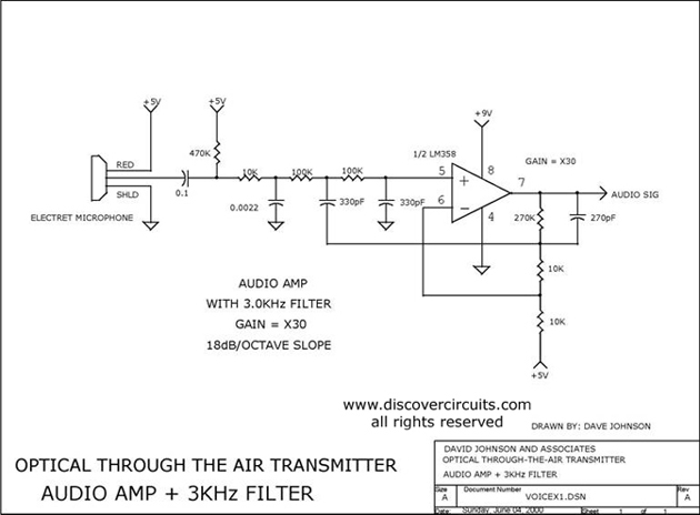
Audio amplifier with a 3 kHz filter. This circuit serves as the audio amplification section for a complete optical transmitter. It amplifies and filters voice audio signals from an electret microphone. The audio amplifier circuit is designed to enhance the...