
50MHz frequency counter V-meter & SWR/PWR indicator
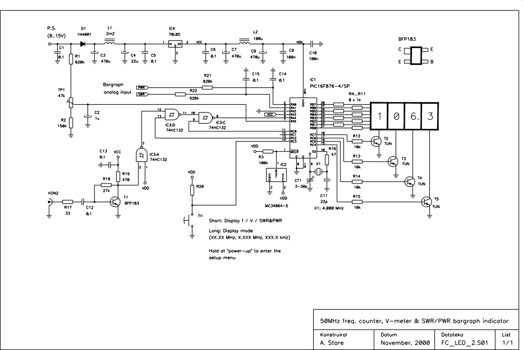
The power-saving mode features automatic display shutdown if no push-button action or frequency change occurs for a specified duration. The display reactivates upon a frequency change or push-button action, with available shutdown time periods of 3s, 10s, 30s, 60s, 120s, 180s, and 240s. This function can be disabled in the setup menu. A programmable frequency offset can be added or subtracted from the measured frequency, settable in the range of 0 to 99,999.9 kHz, which is particularly useful for heterodyne-type RX/TX.
In operating mode, a push-button allows the user to toggle between displaying frequency, bar graph, or supply voltage. The frequency display mode can also be altered with a longer (>1s) push-button press. For instance, if the displayed frequency is 14.065.9 MHz, the user can see "065.9", "4.065", or "14.06" on the four-digit display. The default display mode after power-up can be modified in the setup menu, which is accessed at power-up while holding the push-button.
Due to the discontinuation of Siemens’ (now Infineon’s) miniature 7-segment LED HDN1077 displays in the low current version (suffix O), an alternative display PCB has been designed that is compatible with the existing frequency counter base board, now utilizing Agilent’s HDSP-U103 miniature 7-segment LED displays. These newer displays consume even less current, requiring no more than 0.5mA per segment for adequate brightness. Assuming that, on average, half of the segments are illuminated during normal operation, the average current consumption of the counter is approximately 20mA. In power-saving mode, this consumption drops to less than 10mA, making it suitable for battery-powered applications.
The latest software version of the frequency counter is available for radio amateur and non-commercial use, downloadable for free. The PIC controller is in-circuit programmable if the MC34064 reset circuit is not soldered to the PCB. Installation of this IC is strongly recommended once the frequency counter has been constructed and tested. For proper configuration of the PIC controller settings, contact via email is suggested.This is a successor of the PIC16C71 4-digit LED f-counter & V-meter. Some hard to find parts used in the previous version, which are out of production for some time, has been omitted. A rather early PIC16C71 has also been replaced by 28-pin device PIC16F876. The later is capable of driving 4 digit LED display in multiplexed mode while measuring fr equency, power supply voltage as well as handle two analog inputs to display SWR/PWR signal strength in a bargraph manner. There is no need for external LED display driver chip as well as external data EEPROM since it is already implemented in PIC16F876.
Reduction in the number of used chips also results in smaller dimensions of the counter compared to its predecessor. Measurement of the input voltage at two analog inputs, simultaneously displayed as bargraph (PWR/SWR or S) indicator.
The input sensitivity could be chosen between 0. 25V, 0. 5V, 1. 0V and 2. 0V for maximum bargraph indication. Power save mode: Automatic display shut-down in case the push-button action or frequency change does not occur for a certain time. Display switches on againt after frequency change or push-button action. The available shut-down time periods are 3s, 10s, 30s, 60s, 120s, 180s and 240s. This function can be disabled in set-up menu. Programmable frequency offset added or subtracted from measured frequency, settable in the range of 0 to 99, 999.
9 kHz. This is convenient for use with heterodyne type of RX/TX In operating mode a push-button allows the user to choose between the frequency, bargraph or supply voltage to be displayed. The frequency display mode can also be changed with longer (>1s) push-button pressing. For example if the frequency to be displayed is 14. 065. 9 MHz the user will see on the four digit display either "065. 9", "4. 065" or "14. 06". The default display mode after power-up can be changed in the set-up menu. The set-up menu is entered at power-up while holding the push-button pressed. The production of Siemens`s (now Infineon`s) miniature 7 seg. LED HDN1077 displays in low current version (suffix O) was abandoned recently. Therefore I`ve designed another display PCBoard which suits the same f-counter base board but uses newer Agilent`s HDSP-U103 miniature 7 seg.
LED displays. Their current consumption is even smaller. They need no more than 0, 5mA per segment for acceptable brightness. Assuming that during normal operation in average only one half of the segments lights, the average current consumption of the counter is about 20mA. In power-save mode the consumption reduces to less than 10mA which is important in case of battery powered equipment.
The latest software version of the frequency counter is for radio-amateur and non-commercial use downloadable from this page for free. The PIC controller is in-circuit programmable if the MC34064 reset circuit is not soldered to the PCB.
The instalation of this IC is strongly recommended after the frequency counter has been built and tested. Please contact me for proper PIC controller configuration bits settings by e-mail (aleksander. stare@siol. net). 🔗 External reference
Related Circuits
The design involves creating a circuit and programming for a stepper motor controller, developing a speed-controlled DC motor circuit for the propulsion system of the project, and designing a navigation system using a MEMS accelerometer circuit. This section deviates...
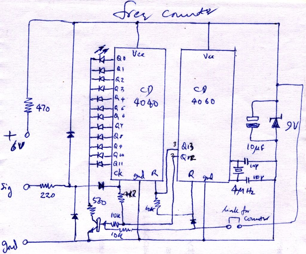
The construction is nearly complete, and a circuit diagram has been created. The design has been finalized and documented on paper. The circuit diagram represents a critical stage in the development of an electronic project, serving as a blueprint for...
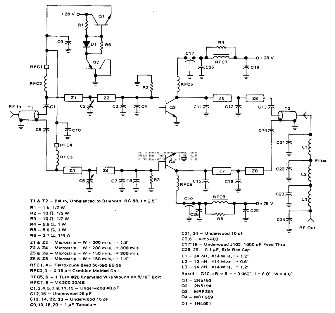
This 100-watt linear amplifier can be built using two MRF309 transistors in a push-pull configuration, requiring only 16 watts of drive power within the frequency range of 420 to 450 MHz. It operates from a 28-volt supply and achieves...
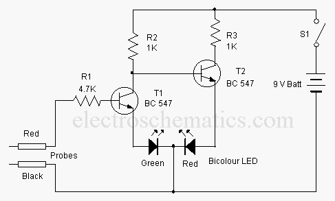
This is a basic logic state indicator designed to test whether the output of a digital integrated circuit (IC) is in a logic high (1) or logic low (0). The bicolor LED illuminates green when the logic state is...
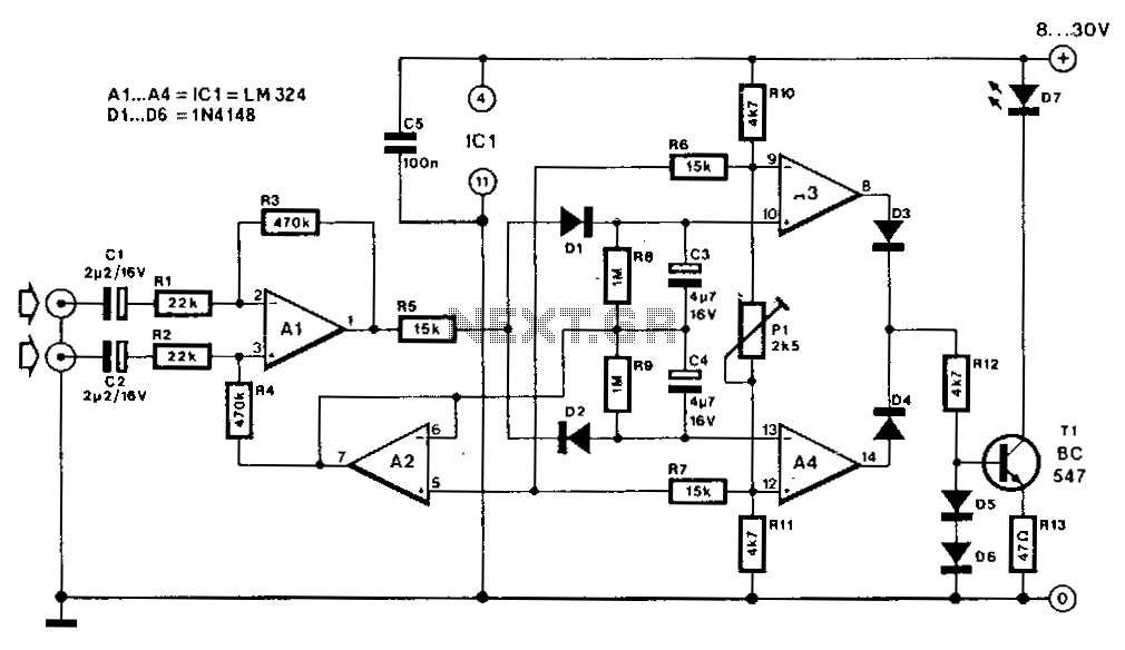
On most FM tuners, the stereo indicator activates upon detection of the 19-kHz pilot tone. However, this does not guarantee that the program is actually stereophonic, as the pilot tone is frequently transmitted alongside mono programs. A similar scenario...
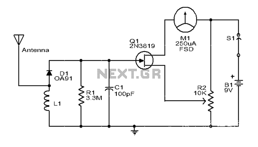
This is a simple and low-cost broadband high-frequency electric field strength meter. The field strength of the radio signal is converted into a DC measurement for analysis. The signal is captured by a coil and processed through a diode...