
automatic light controller circuit diagram
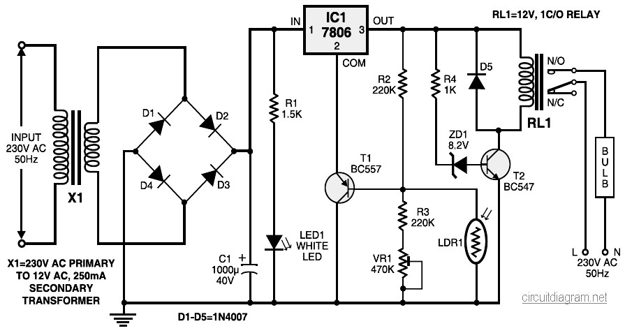
The automatic light controller circuit is designed to operate efficiently in low-light conditions by utilizing a light-dependent resistor (LDR). The high resistance of LDR1 during nighttime ensures that transistor T1 remains off, preventing current flow to the common terminal of IC1. This feature allows the circuit to divert the full input DC voltage to the output, activating transistor T2, which in turn energizes the relay to power the bulb.
The 78xx voltage regulator series plays a crucial role in maintaining a stable output voltage, ensuring that fluctuations in the input supply do not affect the performance of the circuit. The grounding of the common terminal is essential for the proper functioning of the voltage regulator, as it allows any voltage above ground to be added to the output voltage, ensuring reliable operation.
In scenarios where mains power is lost, the circuit automatically switches on the emergency light, providing illumination when it is most needed. The inclusion of overcharge protection in the battery charger circuit enhances the safety and longevity of the battery used in conjunction with this system.
The traffic light controller circuit serves as an educational tool, demonstrating the basic principles of traffic light operation using commonly available components. This circuit is particularly beneficial for teaching children the rules of traffic management in a practical and engaging manner.
The staircase light circuit is designed with user convenience in mind, incorporating a timer that can be adjusted to suit individual needs. This feature allows for automatic switching off after a predetermined duration, ensuring energy efficiency while providing necessary lighting during stair navigation.
The dark and light sensor circuit exemplifies a fundamental application of photoresistors in electronic designs. The inclusion of a potentiometer allows for fine-tuning the sensitivity of the circuit, making it adaptable to various lighting conditions.
Lastly, the sound-activated light circuit showcases the versatility of transistors in signal amplification. The combination of the condenser microphone and transistors enables the detection of sound and subsequent activation of lighting, demonstrating an innovative approach to lighting control based on environmental stimuli.During nighttime, when no light falls on LDR1, it offers a high resistance at the base junction of transistor T1. So the bias is greatly reduced and T1 doesn`t conduct. Effectively, this removes the common terminal of IC1 from ground and it directs the full input DC to the output.
Transistor T2 conducts and the relay energises to light up the bulb as mains connection completes through the relay contacts. This is the circuit diagram of automatic light controller which use 78xx voltage regulator IC series. The voltage regulator ICs deliver a constant output voltage, as against a extensively fluctuating input supply, when the common terminal is grounded.
Any voltage about zero volt (ground) interconnected within the common terminal is added to the output voltage. . The schematic diagram shown right here is the automatic switching-on emergency light circuit which is controlled using IC.
The most important capabilities of this circuit are: automatic switching-on of the light on main power failure and battery charger with overcharge protection. When mains electrical power is absent, relay RL2 is in deenergised state, feeding DC. Here the simple traffic light controller which is could be used to educate kids rudiments of traffic light guidelines.
The circuit utilizes easily available electronic parts. It generally consists of rectifier diodes (1N4001), a 5V regulator 7805, two timers circuit using IC 555, two relays (5V, single-changeover), three 15W, 230V light bulbs and also several. This is the circuit diagram of staircase light with automatic switch off. It based on timer which is can be adjusted with the needs of the time of walking (climbing up and going down) on the staircase.
We have been all acquainted with all the electrical wiring design that joins an electrical bulb with two. This is the basic dark and light sensor which using photoresistor as sensing component. The transistor act like as a switch, when the "switch" in on condition then the relay will be activated.
The potensiometer adjust the trigger `on` level. The diode in the circuit diagram shows to be 1N914. This is ok if you. How this sound activated light works: The condenser microphone fitted inside a position to catch the sound and generates AC signals, which pass by means of DC blocking capacitor C1 for the base of transistor BC549 (T1). Transistor T1 as well as transistor T2 amplifies the sound signals and delivers current pulses within the collector.
🔗 External reference
Related Circuits
The circuit functions as both a latch output and a non-latched output. The control switch, labeled SB, governs the operation. When both SB and VDD are activated, the circuit enters the latch output state, allowing the sixteen output terminals...
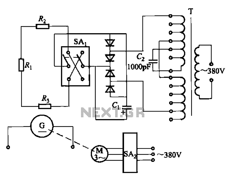
The AR-300 DC arc welding machine circuit includes the AX, AX1, AX3, and AR series. The structure of these machines is fundamentally similar, consisting of a three-integral unit converter, a phase asynchronous motor, and a DC arc welding generator...
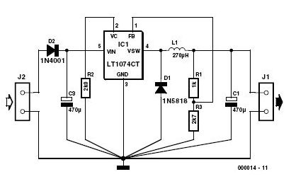
This 3-volt car adapter circuit is based on a standard LT1074CT switching regulator IC. The schematic shows the LT1074CT used as a positive step-down regulator. The 3-volt car adapter circuit employs the LT1074CT, which is a high-efficiency switching regulator capable...

An astable multivibrator is an electronic configuration that generates continuous alternating high and low pulses from two outputs operating in tandem. The IC 4093 consists of four individual NAND gates in one package, specifically Schmitt trigger types, which provide...
The circuit is a temperature-to-pulse-width converter. The LM3524 is used to convert the output of an LM135 temperature transducer into a pulse width that can be measured by a digital system, such as a microprocessor-controlled data acquisition system. In...
A sensitive and reliable RF field strength meter is an invaluable instrument in amateur radio and radio-controlled model applications. This field strength meter is utilized to align antennas for optimal gain and to determine the transmission range of radio...