
Changes to the MXMs Audio Signal Path
The five-input mixer design incorporates a series of enhancements aimed at modernizing the audio signal path while maintaining the integrity of the original circuitry. The introduction of solid-state buffers ensures that each preamp channel can deliver a direct output without compromising the performance of the preceding tube stages. The high input impedance of 1 M-ohm for the output buffers is crucial for preserving signal fidelity and minimizing interaction with the tube preamps.
The modifications to Channel 1 illustrate a significant simplification in the input selection process. The removal of the rotary switch and phono EQ circuitry reflects a shift towards a more streamlined design, focusing on the most relevant input options for contemporary users. By replacing the complex input switching mechanism with a straightforward toggle switch, the design not only enhances usability but also reduces potential points of failure.
The choice of capacitors for coupling applications is critical in audio circuits, and the selection of Sprague "Orange Drop" polypropylene film capacitors highlights a commitment to quality components known for their acoustic properties. This choice is particularly relevant in the context of audio applications where fidelity and tonal characteristics are paramount.
The adjustments made to the microphone input circuitry ensure compatibility with modern microphones while retaining the original design's performance characteristics. By measuring and confirming input impedances, the modifications can be validated against original specifications, ensuring that the mixer meets contemporary standards without sacrificing its vintage appeal.
Overall, these enhancements reflect a careful balance between modernization and respect for the original design, ensuring that the mixer remains relevant in today's audio landscape while retaining its historical significance.As shown by the block diagrams in Figure 1, overall signal flow in this five-input mixer was minimally changed upon modification, but I added solid-state buffers that drive independent direct outputs for the five preamp channels. For each channel, the audio signal for the respective op amp-based buffer is taken from the channel fader`s wiper.
Thu s, channel faders are used to set direct output levels concurrently with relative mix levels in the modified MXM. I designed the channel output buffers to have high impedance inputs (1 M-ohm), which minimally load the preceding tube preamp stages (see below and Figure 10 ).
Other changes to the signal path visible by comparing the block diagrams ( Figure 1 ) are: (1) simplification of Channel 1`s input options, and (2) elimination of the original "high-impedance" unbalanced mix output, with use of a solid-state output buffer instead. I present these modifications in greater detail below. As an overall upgrade to the MXM`s signal path, I replaced all of the original coupling capacitors. In most cases I chose Sprague "Orange Drop" polypropylene film units (this is most apparent in Figure 3, bottom), which are famous for their musicality.
Originally, Channel 1 had a three-position screwdriver-slotted rotary switch on the front panel to select between microphone, phonograph and auxiliary inputs. As seen in Figure 5, this three-pole (3P3T) switch not only selected the input coupling, but also swapped filters within a feedback network (between 7025 triode stages) to add equalization (EQ) for the phono setting.
Passive filter networks at the "magnetic" and "crystal" phono inputs contributed additional EQ for the different 1960s-era phono cartridges. This EQ is obsolete by modern standards, as are monaural phonographs. I therefore eliminated all EQ in this channel rather than attempting to rebuild it. A third setting of Channel 1`s input selector switch completely bypassed the preamp, coupling the auxiliary input jack directly to the top of the channel fader.
Not anticipating much use for this, I opted to eliminate this luxury for simplicity`s sake. Figure 7 (top) shows a schematic of Channel 1 after my modifications. The 3P3T switch and phono EQ circuitry is replaced by a SPDT toggle that simply selects between a transformer-coupled mic input and a 1/4-inch line input. The feedback network between 7025 triode stages is identical to that of the original design when the microphone option was selected.
It results in a flat audio frequency response as the sole option in the modified channel. A Neutrik 1/4-inch jack provides a "line" input when selected by the toggle switch, and is isolated with a series 33 K-ohm resistor for stability. The 1-M-ohm grid resistor at pin 7 of the 7025 tube insures a ground path for any grid current, and also sets the input impedance of the line input to 1 M-ohm.
Accounting for this added resistor, I changed the microphone transformer`s load resistor from 100 to 111 K-ohm, so the equivalent mic input circuits of Channel 1`s original and modified designs are identical. After modification, I measured this channel`s microphone input impedance as 320 ohms. Aside from upgrading their coupling capacitors, I left the design of these pentode-based mic preamp channels the same as in the original MXM (compare the post-modification schematic in Figure 7 [bottom] with the original schematic in Figure 5 ).
However, I eliminated the 9-pin "remote control" jack and its wiring to the pentodes` second grids. This obsolete feature could only be a noise antenna now. On testing the completed project, input impedances for these channels measured exactly 150 ohms. Figure 8 shows a schematic of the MXM`s remaining tube audio circuits after modification. As detailed below, I substituted an op-amp-driven line output for the original "high impedance" master channel output. Otherwise, I upgraded capacitors without altering this se 🔗 External reference
Related Circuits
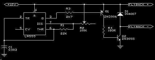
A 555 is used as an oscillator, optimally around 15.76KHz (in North America). Power pins on the chip (pin 1 to ground, pin 8 to +12V) are not shown on the diagram. The output from the 555 is then...
The following circuit diagram depicts a 100 Watt audio power amplifier, constructed using the LM3886 power amplifier chip. A single LM3886 IC can amplify audio power output up to 68W. In this circuit, two LM3886 chips are configured in...
18W audio amplifier constructed using transistors. The 18W audio amplifier design utilizes a transistor-based configuration to achieve efficient amplification of audio signals. The circuit typically consists of several stages, including a preamplifier stage, a driver stage, and a power output...
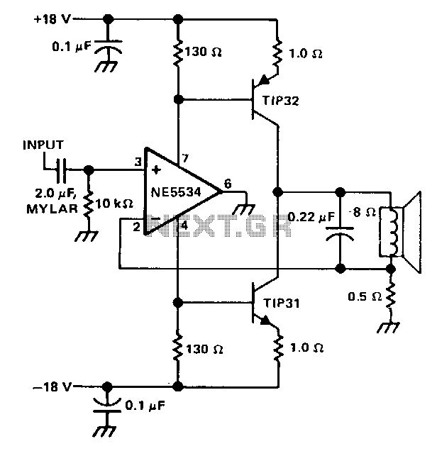
The single speaker amplifier circuit utilizes current feedback instead of the more commonly used voltage feedback. The feedback loop originates from the junction of the speaker terminal and a 0.5-ohm resistor, connecting to the inverting input of the NE5534...
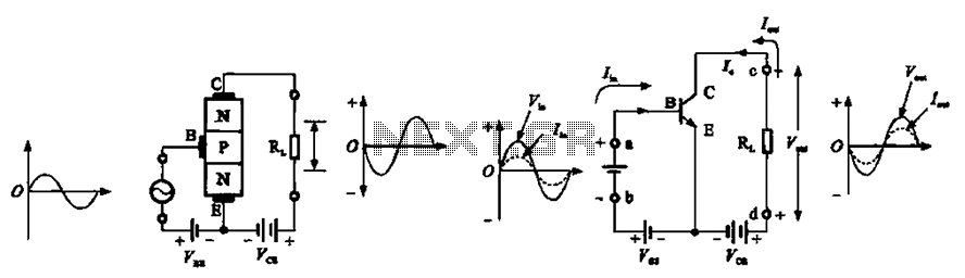
The common emitter amplifier circuit exhibits a specific phase relationship between its input and output signals. This configuration is widely utilized in various electronic devices primarily for its high voltage gain. However, the output impedance is higher than the...
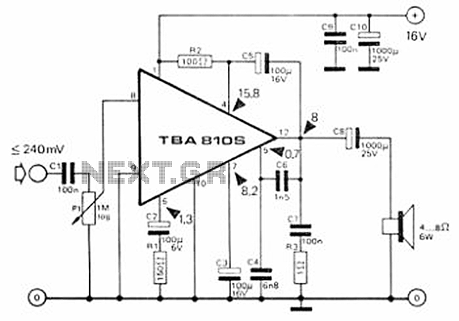
This circuit is a 7 Watt audio amplifier that is simple and easy to construct. It utilizes the TBA810 as the primary component, supported by a few passive components. The amplifier operates effectively, and the necessary kits and components...