
charger
The described circuit utilizes a Vero board, a popular prototyping platform known for its simplicity in creating electronic circuits. The choice of a large electrolytic capacitor instead of a battery for testing purposes allows for observing the circuit's behavior without the risk of battery damage from incorrect charging conditions.
The 500-ohm preset resistor plays a crucial role in setting the output voltage of the circuit. By adjusting this resistor, the user can fine-tune the voltage level to meet the requirements of the connected load or battery. The output voltage is critical for ensuring that the connected device operates correctly and efficiently.
The 47k preset resistor is integral to the hysteresis control mechanism. Hysteresis is essential in preventing the circuit from rapidly toggling on and off around the threshold voltage, which could lead to instability. By setting a specific voltage at which the charger reactivates, the 47k resistor helps ensure that the battery remains charged without entering a state of overcharge. This feature is particularly important for prolonging battery life and maintaining optimal performance.
The cycling behavior of the circuit is indicative of a charge control system, which is designed to monitor battery voltage levels and adjust the charging state accordingly. When the voltage drops below a predetermined level, the circuit activates to recharge the battery. Once the battery reaches the desired voltage, the circuit deactivates, preventing overcharging. This on-off cycling continues, ensuring a consistent and safe charging process.
In conclusion, the described circuit is a well-designed solution for battery charging applications, featuring adjustable output voltage and hysteresis control to enhance performance and reliability. The use of a Vero board facilitates easy modifications and testing, making it suitable for prototyping and development purposes.The circuit was built on Vero board and tested using a large value electrolytic capacitor instead of a battery. The 500 ohm preset resistor sets the actual output voltage. The 47k preset controls the hysteresis and sets the voltage at which the charger switches on again. The circuit will cycle on and off and if correctly set will keep the b attery charged without overcharging it. 🔗 External reference
Related Circuits
A straightforward method for charging a battery using a higher voltage source is illustrated in the accompanying circuit diagram. The circuit requires only one resistor to establish the desired charging current, which can be determined by dividing the voltage...
Most mobile chargers lack current and voltage regulation, as well as short-circuit protection. These chargers typically provide unregulated 6-12V DC for charging battery packs, which generally have a rating of 3.6V and 650mAh. To enhance battery life, it is...
This circuit will not function unless the battery to be charged is connected with the correct polarity. The voltage of the battery regulates the charger, and when the battery is fully charged, the charger will stop supplying current to...
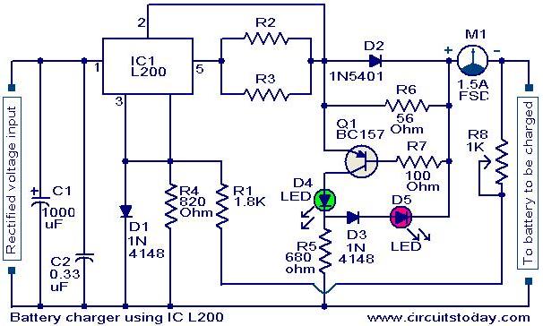
A simple battery charger circuit with reverse polarity indication is presented here. The circuit utilizes the L200 integrated circuit (IC), which is a five-pin variable voltage regulator. The charging circuit can be powered by DC voltage from either a...
NiCd battery charger schematic and description. This NiCd battery charger circuit can charge 12V, 6V, and 9V battery packs. The NiCd battery charger circuit is designed to efficiently charge nickel-cadmium (NiCd) batteries, specifically those with voltage ratings of 12V, 6V,...
The schematic diagram presented is a standard constant current model with an added current limiter, which includes components Q1, R1, and R4. When excessive current flows, it biases Q1 and reduces the output voltage. The output voltage is calculated...