
Charger Extends Lead-Acid Battery Life
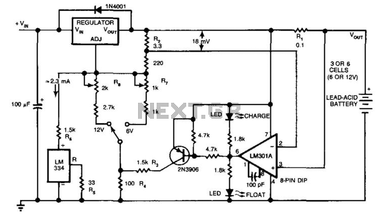
The circuit is designed to efficiently manage the charging process of a rechargeable battery, ensuring optimal performance and longevity. Initially, the circuit applies a charging voltage of 2.5 V per cell, which facilitates rapid charging at a standard temperature of 25°C. As the battery reaches its charge capacity, the charging current naturally decreases. At the threshold of 180 mA, a critical point is reached where the circuit transitions to a float charging mode, lowering the output voltage to 2.35 V per cell. This adjustment is crucial to prevent overcharging, which can lead to battery damage or reduced lifespan.
The LM301A operational amplifier plays a pivotal role in monitoring the charging process. It continuously compares the voltage drop across resistor R1 against a stable reference voltage of 18 mV set by resistor R2. When the current flowing through R1 drops below the specified threshold, the comparator's output signals the voltage regulator to switch to the lower float voltage, thereby maintaining the battery in a safe, fully charged state.
The difference between the charging voltage and the float voltage, quantified at 150 mV, is maintained by the precise ratio of resistors R3 and R4. This ratio is critical for ensuring that the transition between charging and floating voltages occurs at the correct moment, thus optimizing the charging cycle.
Additionally, the circuit features visual indicators in the form of LEDs, which provide real-time feedback on the operational status of the circuit. These indicators can help users quickly ascertain whether the battery is in the charging phase or has transitioned to float mode, enhancing usability and monitoring. Overall, this circuit design exemplifies a robust approach to battery management, balancing efficiency with safety to prolong battery life. The circuit furnishes an initial charging voltage of 2.5 V per cell at 25°C to rapidly charge a batt ery. The charging current decreases as the battery charges, and when the current drops to 180 mA, the charging circuit reduces the output voltage to 2.35 V per cell, floating the battery in a fully charged state. This lower voltage prevents the battery from overcharging, which would shorten its life. The LM301A compares the voltage drop across R1 with an 18-mV reference set by R2. The comparator"s output controls the voltage regulator, forcing it to produce the lower float voltage when the battery-chaiging current passing through R1 drops below 180 mA.
the 150-mV difference between the charge and float voltages is set by the ratio of R3 to R4. The LEDs show the state of the circuit. 🔗 External reference
Related Circuits
Many later radios utilize four 7-pin valves and require a high tension (HT) supply of 90V at approximately 12mA, and a low tension (LT) supply of either 125mA or 250mA, depending on the specific valves used. The original batteries...
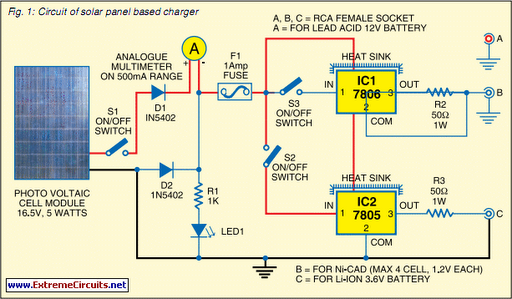
Savings on electricity bills can be achieved by utilizing alternative power sources. The photovoltaic module, or solar panel, described here has a power output of 5 watts and delivers 16.5V under full sunlight conditions, with a current output of...
Switching to alternative power sources can lead to savings on electricity bills. The photovoltaic module or solar panel discussed here has a power output of 5 watts. Under full sunlight conditions, the solar panel generates 16.5V and can provide...
The device serves to quickly establish the status of an indicative power cells. I built it for his children, so they can determine the degree of self-discharge batteries in a variety of toys. WAS tester designed to test the...
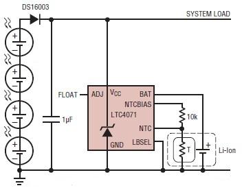
A simple solar-powered battery charger circuit can be designed using the LTC4071 Li-Ion/Polymer Shunt Battery Charger System with Low Battery Disconnect. When VCC reaches the programmed float voltage (4.1V with ADJ floating), the LTC4071 shunts excess current not used...
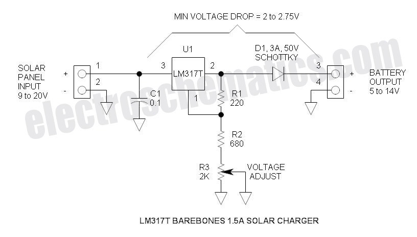
This solar battery charger is a simple and cost-effective project suitable for hobbyists. While it has some limitations compared to other similar devices, it offers several advantages. The charger is designed for lead-acid batteries but can also charge any...