
3 LED - 1 Cell battery tester
The described device is a battery tester designed to assess the state of primary cells, particularly zinc and alkaline types. It features a simple voltage converter and a level indicator to display the battery's status. The tester operates directly from the cell under test, drawing approximately 200 mA at a nominal voltage of 1.5 V. A critical component of the circuit is a low saturation voltage transistor (T1), which is essential for efficient voltage conversion. The tester is designed to withstand a maximum input voltage of 3 V and includes reverse polarity protection.
The circuit consists of two main sections: the voltage converter and the voltage level indicator. The voltage converter is built around the transistor T1, which is configured to maintain high efficiency by minimizing voltage drop. A radial choke serves as the transformer, with approximately 30 turns of enamelled wire wound around it. The output voltage from this section is dependent on the input voltage and is adjusted using resistors R1 and R2.
The voltage level indicator employs low-voltage transistors (T2 and T3) to control the illumination of three LEDs (LED1, LED2, LED3). As the input voltage increases, LED1 lights up first, followed by LED2 and LED3 as the voltage continues to rise. The current through the LEDs is regulated by resistors R3, R4, and R5, ensuring that the LEDs illuminate at specific voltage thresholds. The design allows for differentiation between fresh and partially discharged batteries, as the tester can indicate when a battery has a sufficient open-circuit voltage but a high internal resistance.
The device is housed in a compact box (KP32) with provisions for mounting the printed circuit board (PCB) and the LEDs. The assembly process involves soldering the LEDs onto the PCB after positioning it within the enclosure. For testing and recovery, a regulated power supply is recommended, and a multimeter can be used to verify the operation of the tester. The circuit is designed to be user-friendly, allowing hobbyists to build their own versions with standard components.
The parts list includes standard SMD components, ensuring ease of procurement and assembly. This battery tester provides a practical solution for quickly assessing the health of batteries used in toys and other devices, making it a valuable tool for both enthusiasts and professionals in electronics.The device serves to quickly establish the status of an indicative power cells. I built it for his children, so they can determine the degree of self-discharge batteries in a variety of toys. WAS tester designed to test the fast primary (zinc, alcaline) Cell. Contains simple voltage converter and level indicator. The tester is powered from tested cell. Supply current is depend of cell voltage at 1.5 V and is approx. 200 mA. For high efficiency voltage converting Must be a low saturation voltage transistor T1 Used. Polarity Tester Has Tolerant Input (max. 3 V). The tester is powered from the measured article is loaded with current of 200 mA. Differentiate between the "fresh" part of the old, which, while having sufficient open circuit voltage, but also a large internal resistance. Maximum input voltage is 3 V to the voltage tester is robust against reverse polarity. Tester is designed for primary cells. The measurement of NiCd and NiMH batteries due to a lower voltage LED2 lights up. The batteries are also in the discharge voltage decreases very slowly and the tester can not only determine if the battery is completely discharged.
The test articles could be used as tester - "knives" with a bulb, but such a solution would be difficult to satisfy the amateur electronics. Described here indicates the battery tester of the number of lit LEDs. The involvement of the tester ( Fig. 1 ) can distinguish two parts: a voltage converter and the voltage level indicator. Since the LED needs a supply voltage of about 2 and a fresh battery has only about 1.55 V, was to be used in wiring the drive.
The drive is samokmitající and uncontrolled output voltage is highly dependent on input voltage. This dependence is intentionally increased the use of dividers R1, R2 in the circuit database. A critical part of the drive transistor T1, which have a small saturation voltage. Otherwise, the efficiency rapidly deteriorates. As the transformer is standard radial choke on the secondary winding p?ivineme - about 30 turns enamelled wire with a diameter of about 0.2 mm. Despite the winding piece of shrink tubing drag and a transformer is done. Implementation of the coil is clear from the photo on the picture 2 . The second part is an indicator of stress. With low-voltage transistors T2 and T3 open via resistors R3 and R4, transistors T4 and T5 are closed.
Increases when the voltage, the first light LED1. Upon further increase tension increases LED current until the voltage drop on the R5 T5 opens (probably at 16 mA). The transistor T2 is closed and LED2 voltage increases until it begins to shine. Increases a further power supply current of about 20 mA open and T4. Transistor T3 is closed and illuminates the LED3. For even greater stress is no longer current in a separate indicator not limited to, the tester is limited by power converters.
Power converters, and thus the input voltage, which turns LED3 can be partially affected by changing R1. The tester I built a small box KP32, it is an effective design printed circuit boards, which is partially equipped with SMD.
The coil is horizontally dimensional reasons. For the first LED drill holes in the box, then compose the board with LED in the box and then the LEDs should be soldered into the board. The rear lid of the box, I stuck with the animated tester melt glue. Installation of the small plates is laborious, but nothing to prevent you design your own plate, mounted a classic parts or use a bit of universal plates.
Reviving The recovery is best to use a regulated power supply, then you need a universal measuring instrument, just as the simple multimeter. Connect the tester to the source and slowly zoom in voltage from zero to about 1.6 V. After the mounting plate tester can operate at the first attempt, according to Murphy's Law is very likely to be poorly connected winding N2.
Polarity winding can advance is difficult to establish. Therefore, unless the inverter to oscillate, while the tester to draw current, they will soon end winding N2. If, even after the intervention of the tester did not work, keep gradually its individual parts. First connect the power supply to the capacitor C1 and slowly zoom in tension. When voltage is about 3 V, LED1 lights up when a voltage of approximately 5.5V and LED2 and LED3 8 In.
Up until the power supply current LED3 should not be greater than 20 mA. If the indicator does not work in the manner described, the error in it. If the indicator is correct, check the drive. When increasing the voltage from 0 to 1.6 V C1, the voltage should occur gradually to 8 V and does not oscillate when swapping connection of secondary winding coil does not work, can be T1 or defective diode. It may well be that while the tester is working, but at a voltage 1.5 V does not deliver enough power to light up all LEDs.
Then you can carefully try to change the resistor R1. It does not help if it is still possible to increase the resistance of R5. The illumination of all LEDs will do less delivered current. Parts List R1 470 Ohm, SMD1206 R2 560 Ohm, SMD 1206 R3, R4 2.7 Ohm, SMD 1206 R5 68 Ohm, SMD 1206 C1, C3 In 1947 ?F/10 C2 100 nF, SMD 1206 L1 330 ?H, Choke 09P D1 1N5819, 1 A Schottky T1 BD433 T2 - T5 BC857C SMD LED1 - LED3 standard green LED (2 V/20 mA) Standard Green about 1 m finish. wire dia. 0.1 to 0.25 mm for winding N2 approx. No.33 AWG 3 ft (30 to 36) for wire winding N2 Heat-shrinkable tubing, power wires, test probes Box / Box KP32 PCB / PCB Well.
bcs45 🔗 External reference
Related Circuits
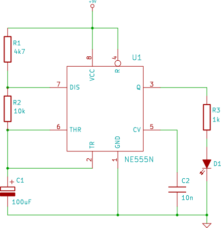
The connection point for the positive terminal of the 9V battery is represented as a circle at the end of a line labeled "+9V." This indicates where to apply power to the circuit. The 0V or "GND" of the...
This simple counter can be used to count pulses, serving as the basis for a customer counter, similar to those found at the entrances of some stores, or for any other application requiring counting. The described simple counter circuit is...

The RCA-83 rectifier utilizes 5VAC for the filament supply. The heaters for the 5687 tubes are powered by a full bridge rectifier consisting of MUR860 diodes, followed by five 10,000µF Elna capacitors. Current regulation is achieved through an LM317...

The circuit illustrated briefly flashes an LED to attract attention and remains illuminated as long as power is supplied. The circuit utilizes the well-known 555 timer integrated circuit (IC) configured as a standard astable multivibrator with resistors RA, RB,...
The heating element is connected in series with two back-to-back 16 amp silicon-controlled rectifiers (SCRs), which are controlled by a small pulse transformer. This pulse transformer features three identical windings: two are dedicated to providing trigger pulses to the...

A diode (IN4148) is utilized as a temperature sensor. IC2 is an A/D converter with BCD output. A reference voltage set by R7 is applied to the positive input of IC2. As the temperature rises, the voltage across the...