
cheap 12v to 220v inverter

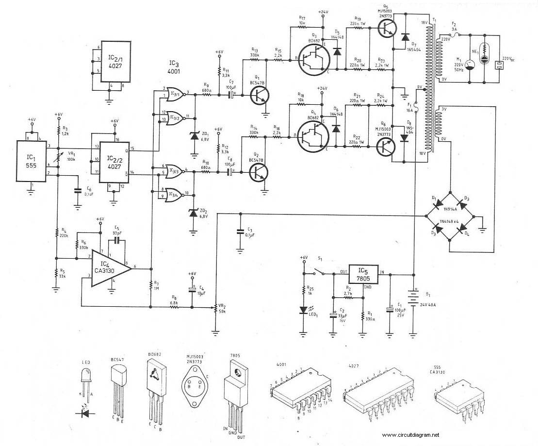
To create a low-power inverter capable of converting DC voltage to 230 V AC at a frequency close to the mains supply, a basic understanding of circuit design and component selection is essential. The inverter circuit typically consists of several key components: a DC power source (such as a battery), an oscillator circuit, a transformer, and a switching mechanism.
The oscillator circuit generates a square wave signal that alternates between high and low states, effectively simulating the AC waveform. Commonly used oscillators include the astable multivibrator configuration using transistors or integrated circuits such as the 555 timer. The frequency of the oscillator can be adjusted to match the desired output frequency, typically 50 Hz or 60 Hz, depending on the regional standards.
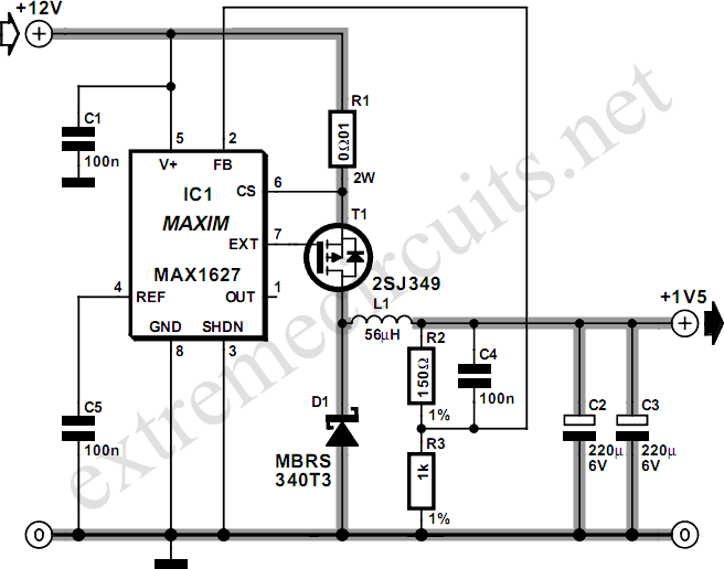
The switching mechanism, often implemented with transistors or MOSFETs, is responsible for controlling the flow of current through the transformer. When the oscillator activates the switches, current flows through the primary winding of the transformer, inducing a voltage in the secondary winding. The transformer steps up the voltage to the required 230 V AC level.
To ensure the inverter operates efficiently and safely, it is crucial to incorporate protective components such as fuses and diodes. Fuses can prevent overcurrent situations, while diodes can protect against reverse voltage spikes, which could damage sensitive components.
Finally, the output of the inverter should be filtered to smooth the waveform, as the square wave produced by the oscillator may not be suitable for all appliances. This can be achieved using capacitors and inductors to create a low-pass filter, effectively converting the square wave into a more sinusoidal waveform.
Overall, constructing a low-power inverter is an accessible project for electronics enthusiasts, providing a practical solution for powering 230 V AC appliances in off-grid scenarios.Even though today s electrical appliances are increasingly often self-powered, especially the portable ones you carry around when camping or holidaying in summer, you do still sometimes need a source of 230 V AC - and while we re about it, why not at a frequency close to that of the mains? As long as the power required from such a source remains relatively low - here we ve chosen 30 VA - it s very easy to build an inverter with simple, cheap components that many electronics hobbyists may even already have..
🔗 External reference
Related Circuits
Most small internal combustion engines commonly used in model building utilize glow plugs for starting. However, glow plugs operate at a voltage of 1.5 V, while components such as fuel pumps, starter motors, and chargers typically operate at 12...
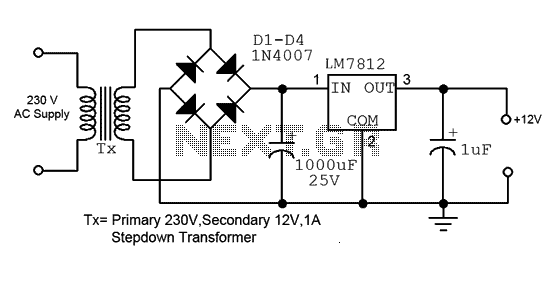
This is a straightforward 12V power supply circuit diagram. It features a fixed voltage output and is based on the LM7812 voltage regulator integrated circuit. The 12V power supply circuit utilizing the LM7812 voltage regulator is designed to provide a...
Ever needed a low power 120volt AC power source for your car, van or truck? Well this circuit should do the trick for you. It will supply 15 watts of AC power to a device. It should power lamps,...
This circuit allows a 12v relay to operate on a 6v or 9v supply. Most 12v relays need about 12v to "pull-in" but will "hold" on about 6v. The 220u charges via the 2k2 and bottom diode. When an...
This is the schematic diagram of a 300W power inverter circuit. The inverter utilizes the MJ15003 power transistor for final amplification. If the MJ15003 transistor is difficult to source, it can be replaced with a 2N3773. The inverter is...
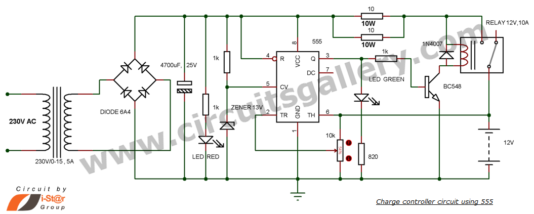
This is a simple DIY charge controller schematic created in response to a request from one of the readers on our Facebook page. The primary component of this automatic battery charger circuit is a 555 timer, which compares the...