
Cheap 12V to 220V Inverter
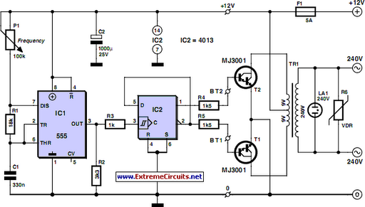
Let`s not forget, for example, that just to get a meager 1 amp at 230 VAC, the battery primary side would have to handle more than 20 ADC!. The circuit diagram of our project is easy to follow. A classic 555 timer chip, identified as IC1, is configured as an astable multivibrator at a frequency close to 100 Hz, which can be adjusted accurately by means of potentiometer P1.
As the mark/space ratio (duty factor) of the 555 output is a long way from being 1:1 (50%), it is used to drive a D-type flip-flop produced using a CMOS type 4013 IC. This produces perfect complementary square-wave signals (i. e. in antiphase) on its Q and Q outputs suitable for driving the output power transistors. As the output current available from the CMOS 4013 is very small, Darlington power transistors are used to arrive at the necessary output current.
We have chosen MJ3001s from the now defunct Motorola (only as a semi-conductor manufacturer, of course!) which are cheap and readily available, but any equivalent power Darlington could be used. These drive a 230 V to 2 G— 9 V center-tapped transformer used backwards` to produce the 230 V output.
The presence of the 230 VAC voltage is indicated by a neon light, while a VDR (voltage dependent resistor) type S10K250 or S07K250 clips off the spikes and surges that may appear at the transistor switching points. The output signal this circuit produces is approximately a square wave; only approximately, since it is somewhat distorted by passing through the transformer.
Fortunately, it is suitable for the majority of electrical devices it is capable of supplying, whether they be light bulbs, small motors, or power supplies for electronic devices. Note that, even though the circuit is intended and designed for powering by a car battery, i. e. from 12 V, the transformer is specified with a 9 V primary. But at full power you need to allow for a voltage drop of around 3 V between the collector and emitter of the power transistors.
This relatively high saturation voltage is in fact a shortcoming` common to all devices in Darlington configuration, which actually consists of two transistors in one case. We`re suggesting a PCB design to make it easy to construct this project; as the component overlay shows, the PCB only carries the low-power, low-voltage components.
The Darlington transistors should be fitted onto a finned anodized aluminum heat-sink using the standard insulating accessories of mica washers and shouldered washers, as their collectors are connected to the metal cans and would otherwise be short-circuited. An output power of 30 VA implies a current consumption of the order of 3 A from the 12 V battery at the primary side`.
So the wires connecting the collectors of the MJ3001s [1] T1 and T2 to the transformer primary, the emitters of T1 and T2 to the battery negative terminal, and the battery positive terminal to the transformer primary will need to have a minimum cross-sectional area of 2 mm2 so as to minimize voltage drop. The transformer can be any 230 V to 2 G— 9 V type, with an E/I iron core or toroidal, rated at around 40 VA.
Properly constructed on the board shown here, the circuit should work at once, the only adjustment being to set the output to a frequency of 50 Hz with P1. You should keep in minds that the frequency stability of the 555 is fairly poor by today`s standards, so you shouldn`t rely on it to drive your radio-alarm correctly but is such a device very useful or indeed desirable to have on holiday anyway Watch out too for the fact that the output voltage of this inverter is just as dangerous as the mains from your domestic power sockets.
So you need to apply just the same safety rules! Also, the project should be enclosed in a sturdy ABS or diecast so no parts can be touched while in operation. The circuit should not be too difficult to adapt to other mains voltages or frequencies, for example 110 V, 115 V or 127 V, 60 Hz.
The AC voltage requires a transformer with a different primary voltage (which here becomes the secondary), and the frequency, some adjusting of P1 and possibly minor changes to the values of timing components R1 and C1 on the 555. 🔗 External reference
Related Circuits
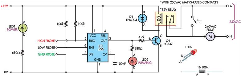
This straightforward yet efficient circuit is designed to manage the water level in a container. The prototype is utilized to pump water out of a bucket that collects condensation from a home air-conditioning system. The design revolves around a...
The working principle of this inexpensive and simple-to-build metal detector circuit involves mixing two equal frequencies, which results in a low-frequency interference. The metal detector circuit operates on the principle of heterodyning, where two frequencies are combined to produce a...

Although LEDs dominate the lighting market today, a standard flashlight bulb can still be a viable light-emitting option, particularly due to its simpler configuration compared to an LED. When the AC mains supply fails, transistor T1 becomes forward-biased, allowing...
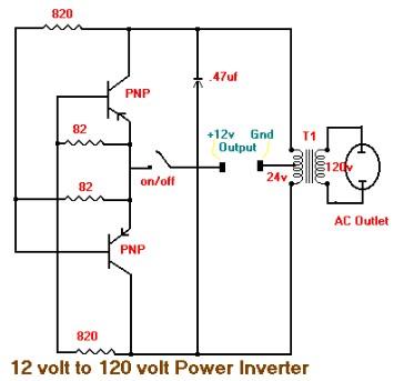
This is the schematic diagram of a 15W inverter circuit. The circuit is based on a PNP power transistor such as the TIP32 and other similar transistors. This inverter produces a square wave output, which may cause some noticeable...

The 78W series voltage regulators are designed to handle an input voltage of approximately 35V, while the 24V type can withstand up to 40V. It should be noted that these regulators will not operate effectively with a significant input-output...
Any step-down DC-DC converter can be utilized as an inverter without modifications to the operating schematic. The only differences between the standard step-down application and the inverting operation are the labels of the connection points. The step-down VOUT is... A...
Warning: include(partials/cookie-banner.php): Failed to open stream: Permission denied in /var/www/html/nextgr/view-circuit.php on line 713
Warning: include(): Failed opening 'partials/cookie-banner.php' for inclusion (include_path='.:/usr/share/php') in /var/www/html/nextgr/view-circuit.php on line 713