
Cheap Metal Detector Circuit
The metal detector circuit operates on the principle of heterodyning, where two frequencies are combined to produce a new frequency. In this case, the circuit typically employs an oscillator to generate two signals of equal frequency. These signals are then mixed in a non-linear component, such as a diode, which creates beat frequencies as a result of the interference between the two signals. The output from this mixing process generates a low-frequency tone that is indicative of the presence of metal.
The circuit generally comprises several key components: an oscillator, a mixer, an amplifier, and a speaker or headphone output for audio feedback. The oscillator can be implemented using a simple LC circuit or a dedicated oscillator IC, providing a stable frequency output. The mixer can be realized with a diode or a transistor configured in a way to facilitate the mixing of the two frequencies.
When metal is introduced into the detection field, it alters the electromagnetic field generated by the oscillator. This change modifies the frequency of the signals being mixed, resulting in a shift in the beat frequency. The amplifier then boosts this signal to a level that can be easily heard through the output device, alerting the user to the presence of metal.
The simplicity of the design allows for easy assembly and low-cost components, making it accessible for hobbyists and educational purposes. This circuit can serve as an excellent introduction to the principles of electronics, frequency mixing, and metal detection technology.The working principle of this cheap and easy to build metal detector circuit consists in mixing two equal frequencies which causes a low-frequency interfer.. 🔗 External reference
Related Circuits
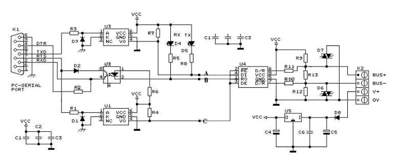
RS232 to RS485 Converter Circuit Schematic. RS232 to RS485 converters are primarily utilized in industrial and commercial settings. The RS232 to RS485 converter circuit is designed to facilitate communication between devices using different serial communication standards. RS232 is commonly found...
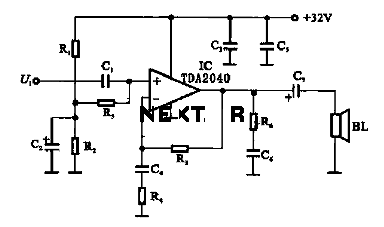
An integrated power amplifier TDA2040 is used in an OTL (Output Transformer-Less) power amplifier circuit, which operates with a +3V single supply as the working voltage. This circuit has a voltage gain of 30 dB (approximately 32 times magnification),...
Before applying power, check for shorts on the board. This design operates from a 5V supply; connecting it directly to a 12V supply will certainly damage it. The current draw is minimal, approximately 70mA, so if using a 12V...
This circuit utilizes a synchronous demodulator to extract a 1 kHz signal from noise and measures its amplitude, with the 1 kHz signal providing a resolution of approximately 60 microvolts per count. The measurements are transmitted via an RS-232...
A highly beneficial project involving a crystal tester circuit, also known as an xtal tester circuit, constructed with only a few components. The circuit forms an oscillator that will only oscillate if the crystal under test is functioning properly....
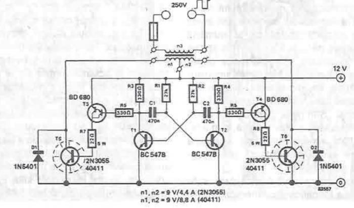
A simple portable converter that transforms 12V to 250V can be constructed using this circuit diagram. This converter is intended for portable use with a 12V car battery. A built astable multivibrator, consisting of transistors T1 and T2, generates...