
Cheap precision digital clock time base oscillation circuit
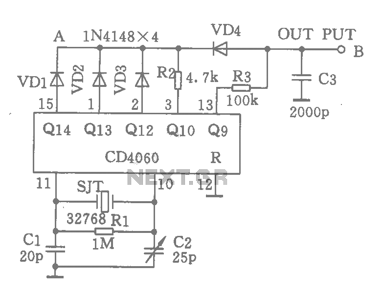
The circuit features additional components, including diodes (VD1, VD2, VD3) and resistors (R2), which form an OR gate configuration. This configuration allows for the generation of various pulse frequencies: 2 Hz, 4 Hz, and 8 Hz, leading up to a 32 Hz output. The output from the CD4060 at pin 13 provides a 64 Hz signal, which can be further processed to yield a 60 Hz output at point B. The capacitor C3 is included to filter out any unwanted pulses generated at point A, ensuring minimal interference. Without C3, the output at point B would remain at 60 Hz.
The schematic consists of the following key components:
1. **CD4060 IC**: This is a binary ripple counter and oscillator. The 32,768 Hz crystal connected to the CD4060 serves as the timing reference, allowing the IC to produce a precise clock signal. The internal divider stages of the CD4060 reduce the frequency stepwise until the desired output frequency is achieved.
2. **Crystal Oscillator**: The 32,768 Hz crystal oscillator is a standard choice for timekeeping applications due to its accuracy and stability. It provides the fundamental frequency that drives the clock circuit.
3. **Diodes (VD1, VD2, VD3)**: These components are used to create an OR gate. The diodes ensure that when any of the input signals are high, the output will also be high, allowing for the combination of multiple pulse frequencies.
4. **Resistor (R2)**: This resistor is part of the OR gate configuration and helps in setting the appropriate current levels through the diodes.
5. **Capacitor (C3)**: This capacitor acts as a filter to smooth out any rapid fluctuations or noise in the signal at point A, ensuring that the output at point B remains stable at 60 Hz.
6. **Output Frequencies**: The circuit is designed to produce multiple output frequencies, including 2 Hz, 4 Hz, 8 Hz, and 32 Hz, which can be utilized for various applications. The final output frequency at point B, which is derived from the 64 Hz signal at pin 13, is crucial for applications requiring a precise 60 Hz clock signal.
This configuration is ideal for applications that demand a reliable and accurate clock source, such as in digital watches, timers, or other electronic devices where precise timing is essential. The simplicity of the design, combined with the accuracy of the CD4060 and the crystal oscillator, makes it a popular choice among electronics engineers.As shown using a cheap CD4060 and 32768Hz crystal to produce highly accurate output 60 pulses per second clock source. The principle is 32768Hz pulse after CD4060 divider output 15,1,2,3 foot 2Hz, 4Hz, after 8Hz, 32Hz pulse input from the VDl, VD2, VD3, R2 consisting of the OR gate, every point A l / 2 sec in 1/32 seconds low, the output of block 13 feet 64Hz signal 2 pulses per second, so you can remove 4 from the 13-pin output 64Hz pulse at point B form irregular 60Hz when the group. C3 is for eliminating the 13 foot point A competitive adventure produced minimal pulse. If no C3, B outputs will remain 60Hz.
Related Circuits
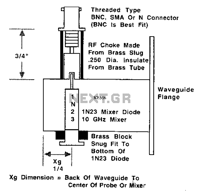
This is a 10 GHz frequency amateur radio waveguide detector. The 10 GHz amateur radio waveguide detector is designed to operate within the microwave frequency range, specifically targeting the 10 GHz band commonly used in various amateur radio applications. The...
This circuit is designed to detect the approximate percentage of salt in a liquid. After careful calibration, it can provide a quick, rough indication of salt content in liquid foods for dietary purposes. The operational amplifier IC1A is configured...
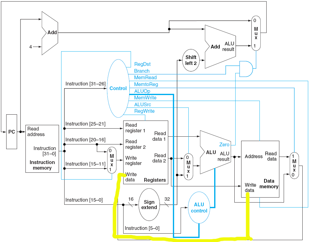
Is it feasible to modify a single-cycle datapath so that an add instruction not only writes to a register but also writes to a specified memory address? The only method considered involves splitting the value as illustrated below. However,...
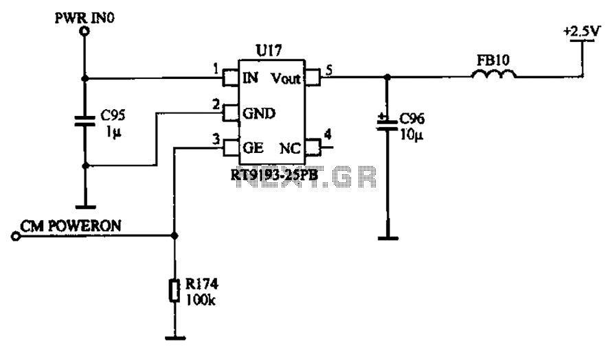
The camera power supply circuit illustrates the essential power supply required for the proper functioning of the camera. This power supply circuit is composed of a stable voltage control integrated circuit. The camera power supply circuit is critical for ensuring...
In spite of the improvement of communication link and despite all progress in advanced communication technologies, there are still very few functioning commercial wireless monitoring systems, which are most off-line, and there are still a number of issues to...
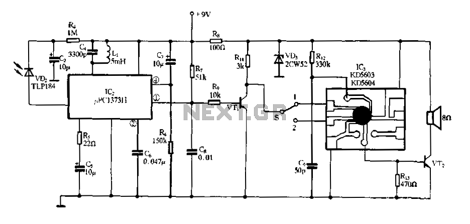
Electronic Miss Manners infrared receiver and voice circuits The Electronic Miss Manners system integrates an infrared (IR) receiver with voice circuits to facilitate communication and interaction. The IR receiver is designed to detect signals emitted from a remote control or...
Warning: include(partials/cookie-banner.php): Failed to open stream: Permission denied in /var/www/html/nextgr/view-circuit.php on line 713
Warning: include(): Failed opening 'partials/cookie-banner.php' for inclusion (include_path='.:/usr/share/php') in /var/www/html/nextgr/view-circuit.php on line 713